Bondable Magnet Wire, Bondable Copper Magnet Wire
BondABLE MAGNET Wire
General
Bondable magnet wire, also referred to as Selfbonding magnet wire, is film insulated wire (  Magnet Wire Types ) which is coated with an additional bonding adhesive.
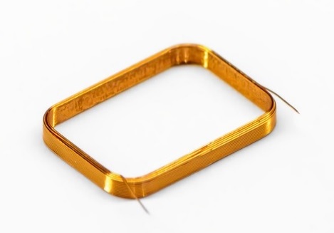
After activating the bondcoat, the individual turns of the coil are bonded together to produce self-supporting coils ("air coils" without bobbin) or special coils for later processing.
Use of bondable magnet wire offers advantages over conventional magnet wire in certain winding applications, eliminating the need for bobbins as well as taping or varnishing steps.
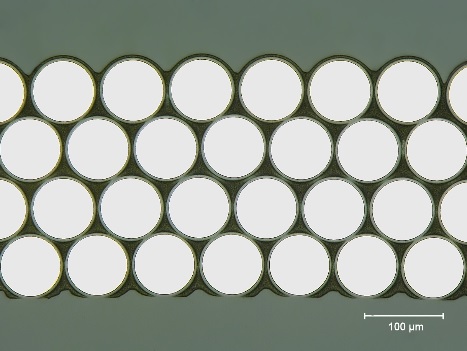
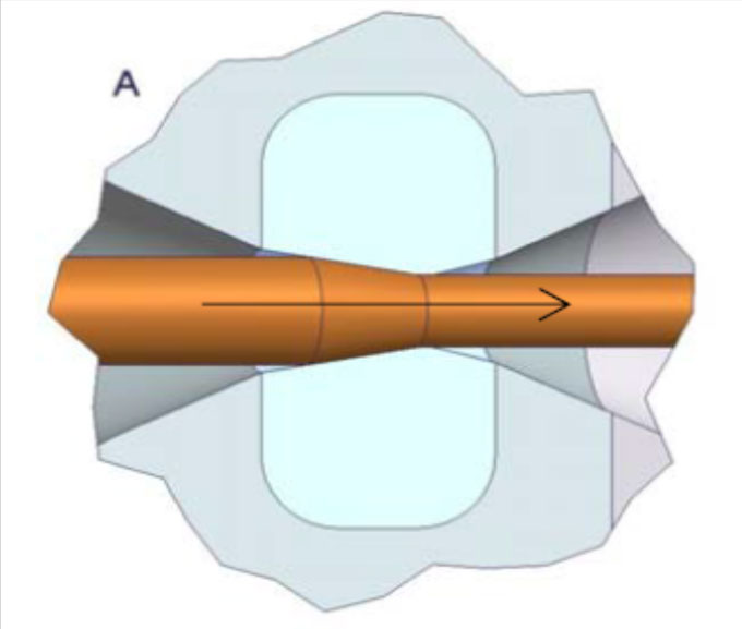
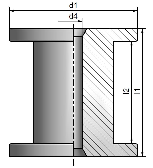
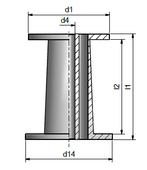
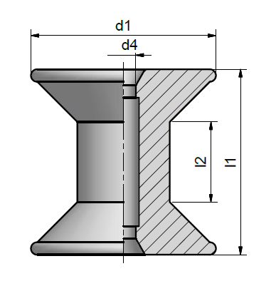
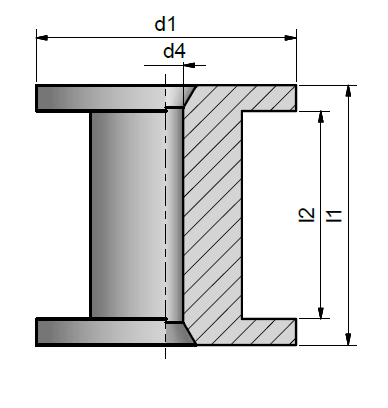
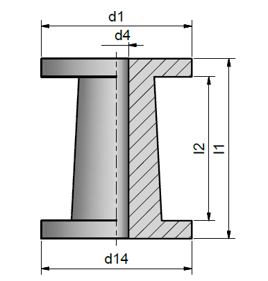
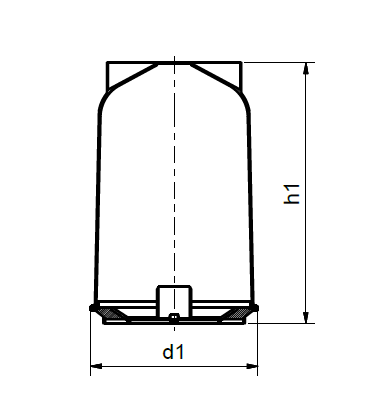
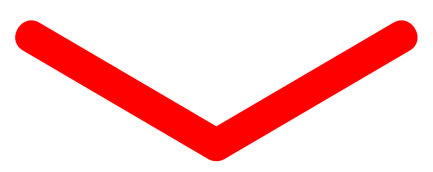
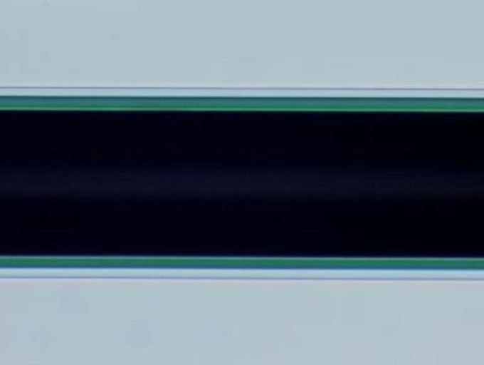
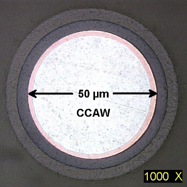
Cross section of wound coil
(Lighter colour = insulation, dark colour = bondcoat)
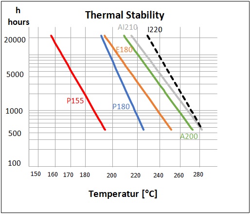
In many applications such as high-power speakers or small motors, bondable magnet wire can improve the performance and reliability. An important property of a bondable magnet wire is the thermal stability of the wound coil at higher temperatures. A thermoplastic bondcoat will become soft at higher temperatures and begin to lose its bond strength, but
could also be processed, for example, to form another shape of a coil and be rebonded at higher temperature. A thermoset bondcoat has higher heat resistant properties, so will lose its bond strength only at a temperature that will destroy the enamel.
Because of the additional application of a bondcoat, selfbonding magnet wire is more expensive than normal wires, which is offset by the value added.
Activation of the bondcoat may be achieved with either heat, or in some cases a solvent, or a combination of the two ( Bonding Processes ).
Our Product Line
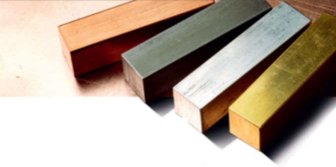
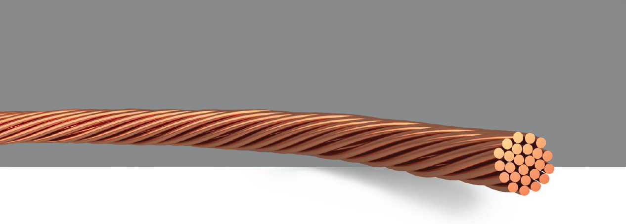
Elektrisola produces bondable magnet wire with diameters of 0.010 - 0.50 mm ( Technical Data by Size ). In addition to copper as a conductor material, other alloys are available, such as Aluminium or Copper Clad Aluminium for light weight coils or high tensile strength conductors for better durability ( Metals ).
Selfbonding magnet wire types can be differentiated by the chemical basis of their coatings, primarily by their thermal properties, by their technical properties and by the preferred bonding method.
The basic bondable magnet wire types offered around the world have differences mainly explained by the history of their development. Therefore Elektrisola offers selfbonding magnet wire types for the 3 major continents
( Selfbonding Wire Types ). In Asia, special high performance bondcoats formulated for use in specific Asian applications are also offered ( High Performance Selfbonding Wire Types ).
In addition to standard selfbonding enamel types, ELEKTRISOLA has its own certified selfbonding enamel development for special applications. For example, in fine wire sizes, specialized ultra-high temperature selfbonding enamel types are now available, which can be wound with automated hot-air winding machines for fast and cost effective processing providing a major advantage to Elektrisola customers.
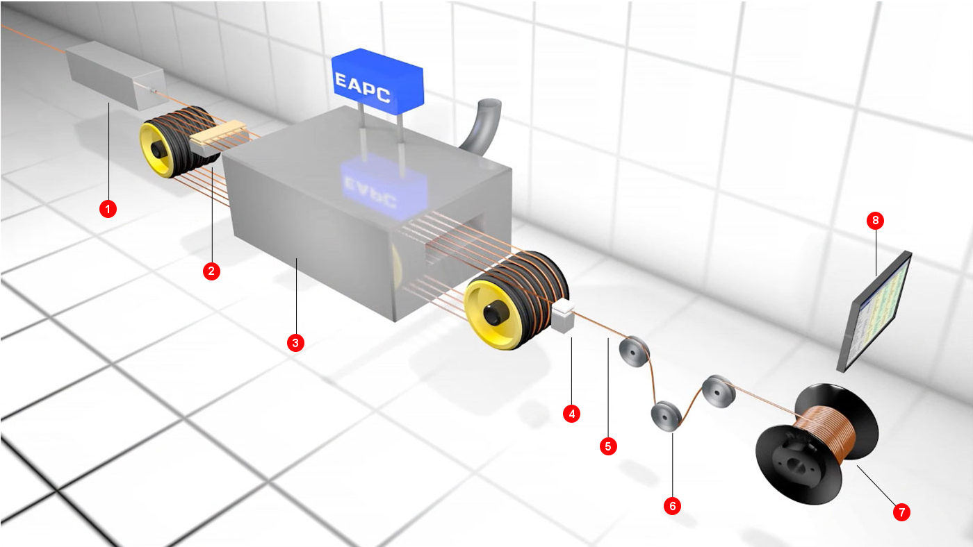
Production Process
The production process of a selfbonding magnet wire is similar to a normal film insulated wire
( Enamelling Process ), but needs 2 enamel applicators, one for the electrical insulation coating, and one for the bondcoat.
Bonding Process
The bondcoat adhesive on the outside of the bondable magnet wire can be activated by heat or with chemicals. These bonding methods are described below.
Heat/Thermal Bonding:
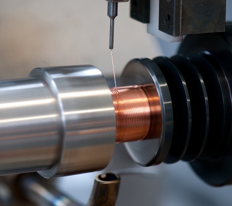
All Elektrisola bondcoats can be activated by heat, either by directing hot air on to the wire during winding, by oven-heating of the wound coil, or by applying electric current to the wound coil after the winding cycle is completed. In any of these examples, the principle is to heat the winding slightly above the bondcoat’s melting temperature in order to activate the bondcoat and bond the wires together.
Hot-air Bonding during winding has the advantage of eliminating the secondary bonding operation. This method is cost effective and primarily used for wire sizes thinner than 0.200 mm. This method became much more popular over the last few years following the development of ultra-high temperature selfbonding enamel types.
Oven Bonding is accomplished by heating the wound coil, which still remains on a fixture or tooling, in an oven at a suitable temperature and time sufficient to obtain uniform heating throughout the winding followed by a cooling cycle. Heating time is generally 10 to 30 minutes, depending on the size of the coil. Disadvantages of oven bonding are the longer bonding time, additional process steps, as well as the potential need for many winding fixtures.
Resistance Bonding is accomplished by applying electric current to the finished coil to electrically heat it by resistance to the proper bond temperature. Bonding voltage and time are dependent upon wire size and coil design, and therefore will need to be developed experimentally for each specific application. This method has the advantages of being quick and generating a quite uniform heat distribution. It is typically used for wire sizes thicker than 0.200 mm.
Solvent Bonding:
Some bondcoats can be activated by applying specified solvents during the coil winding process. Application of the solvent, usually via a saturated felt during winding ("Wet Winding"), causes the bondcoat to become very soft. This process requires the use of a fixture to hold the coil in place while the solvent is drying and the wires stick together. Afterwards, the coil should be heated in an oven cycle to evaporate any residual solvent, which, if left within the coil, might cause long-term coil failure, as well as to complete the adhesive curing process for optimum bond strength.
Applications
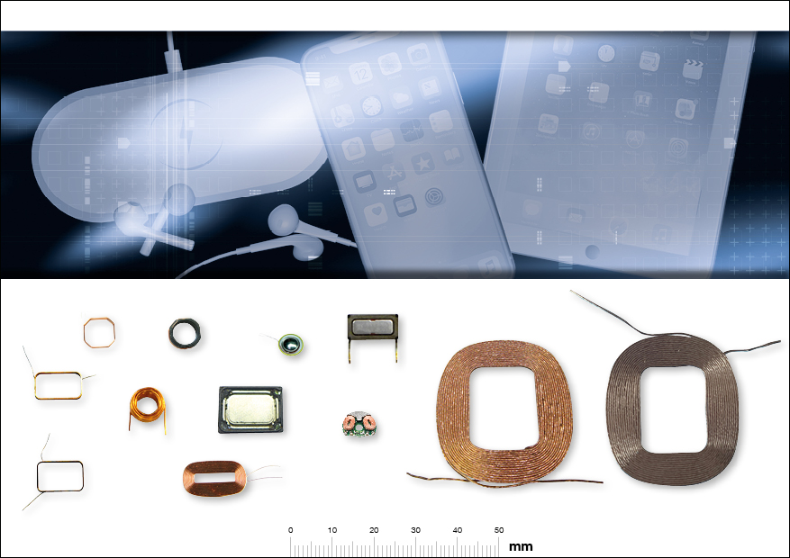
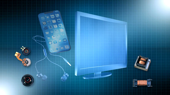
Cellphone
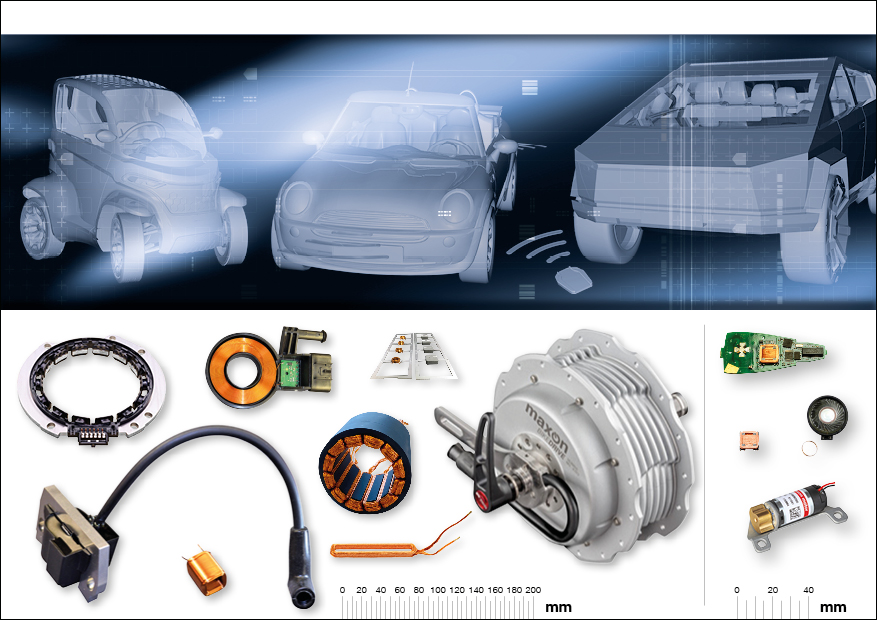
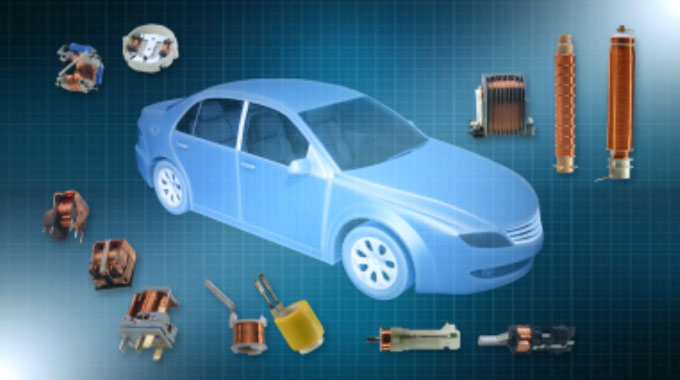
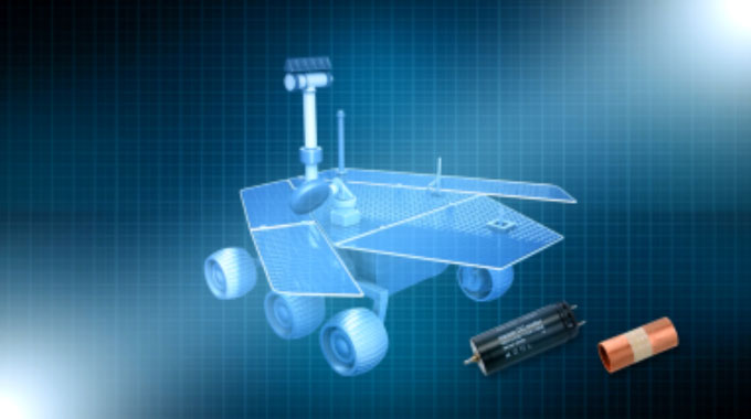
Automotive
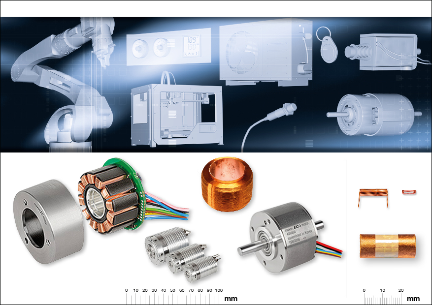
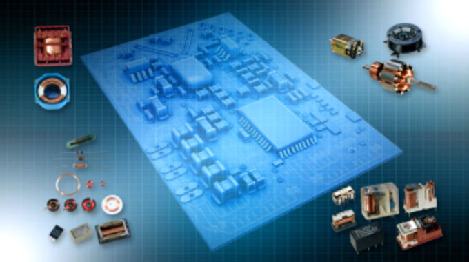
Industrial
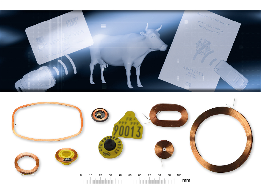
Identification
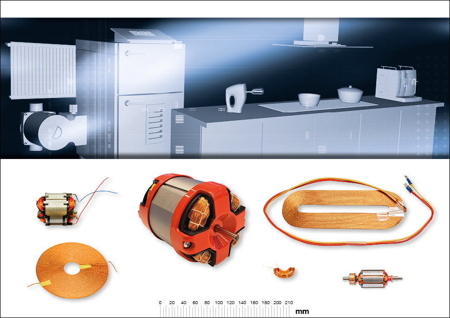
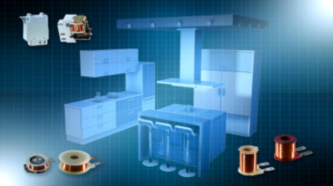
Appliance

Consumer
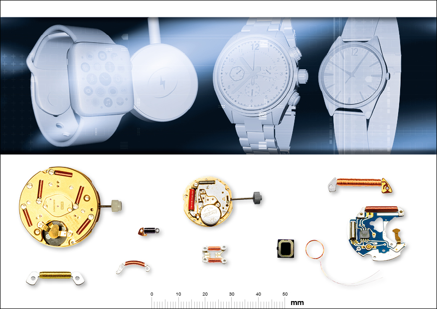
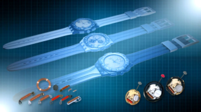
Watches
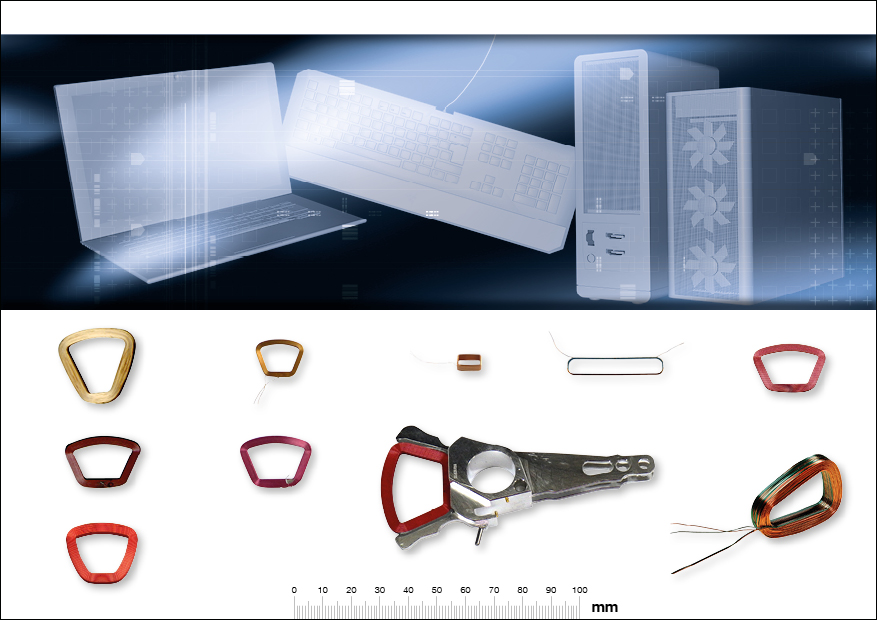
Computer
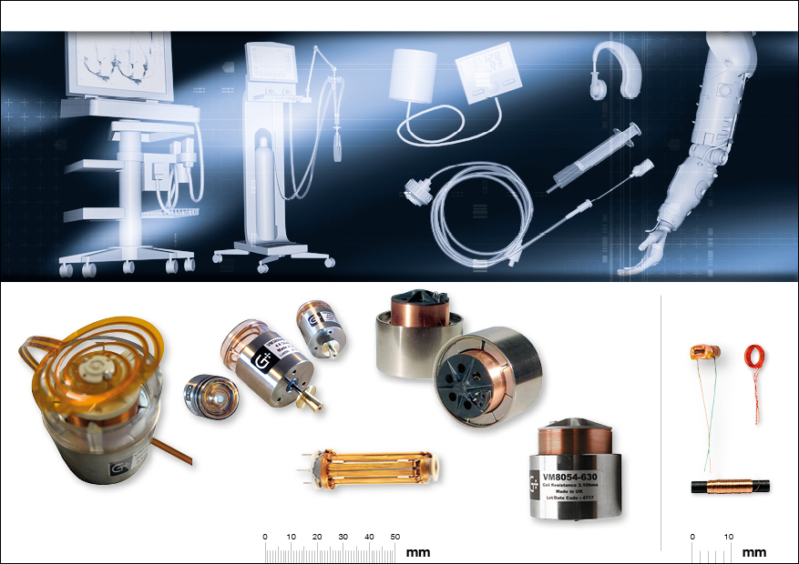
Medical
Advantages OF BONDABLE MAGNET WIRE
The use of bondable magnet wire offers multiple advantages to customers:
- Eliminates the need for bobbins
- No need for taping or varnishing
- Less handling in the process
- Reduced total cycle times
- Improved performance
- Low environmental impact