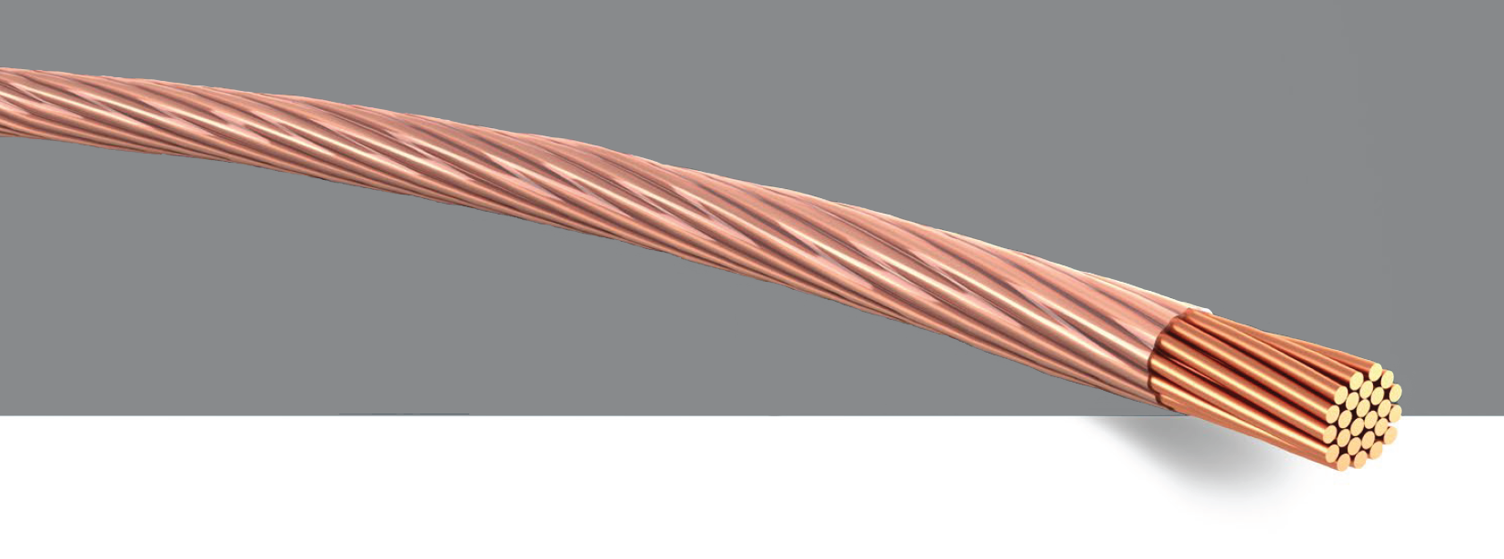
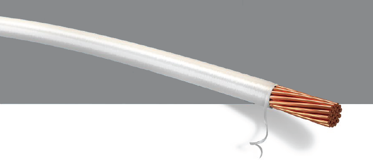
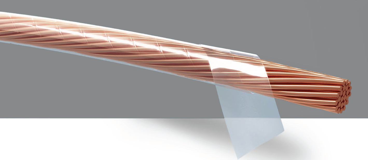
Litz Wire Details
Litz Wire

Single Wire Diameter vs Range of Frequency
| range of frequency [kHz] | dominal diameter of single wire [mm] | ||
|---|---|---|---|
| from | to | from | to |
| 0.06 | 1 | 0.4 | 0.254 |
| 1 | 10 | 0.254 | 0.2 |
| 10 | 20 | 0.2 | 0.127 |
| 20 | 50 | 0.127 | 0.102 |
| 50 | 100 | 0.102 | 0.079 |
| 100 | 200 | 0.079 | 0.063 |
| 200 | 350 | 0.063 | 0.05 |
| 350 | 850 | 0.05 | 0.04 |
| 850 | 1400 | 0.04 | 0.03 |
| 1400 | 3000 | 0.03 | 0.02 |
Influence of Litz Wire Parameters on Litz Wire Freatures
| construction parameters | |||||||||
|---|---|---|---|---|---|---|---|---|---|
| conductor material | nom. diameter single wire ØSW | no. of single wires nSW | no. of bundles & bunching steps | length of lay SL per bunching step | pitch direction SR per bunching step | thickness of enamelling | |||
| litz wire features | electrical | total cross section litz wire AConductor,Litz; direct current resistance RDC | X | X | X | ||||
| high frequency resistance RAC; RF-losses | X | X | X | X | |||||
| current density J = I/AConductor,Litz | X | X | |||||||
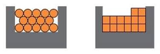
| filling factor litz wire AConductor,Litz/Atot,Litz | X | X | X | X | X | ||||
| breakdown voltage UBDV | X | ||||||||
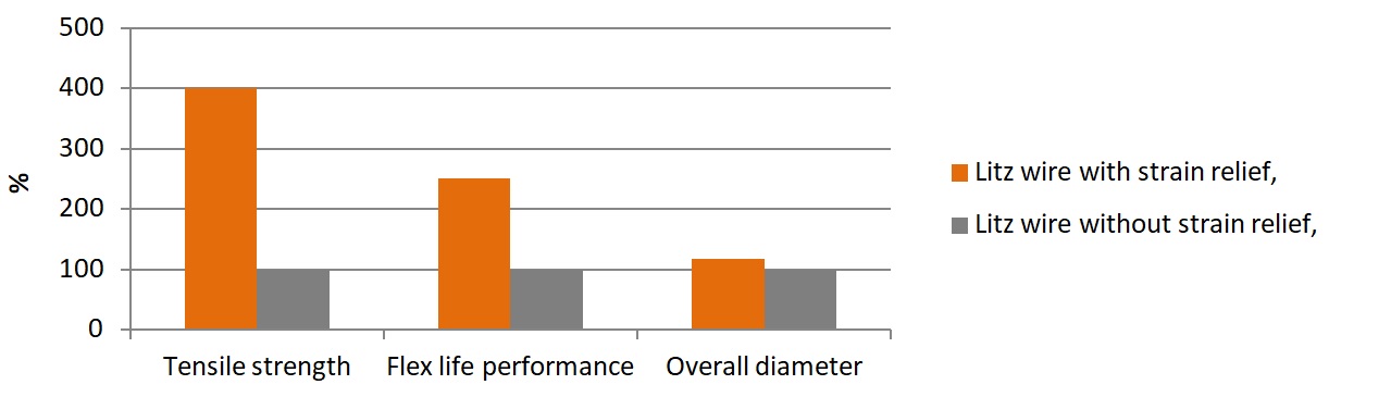
| mechanical (AConductor,Litz = const.) | outer diameter ODLitz;total cross section litz wire Atot,Litz | X | X | X | X | X | X | X | |
| dimensional stability | X | X | X | X | X | ||||
| flexibility | X | X | X | X | |||||
| flexlife performance | X | X | X | X | |||||
| max. tensile strength | X | ||||||||
| surface structure, roundness | X | X | X | X | X | ||||
Main influencing parameters for HF-coils
| construction parameters | |||||||
|---|---|---|---|---|---|---|---|
| nom. diameter single wire ØSW | number single wires nSW | number bundles & bunching steps | length of lay SL per bunching step | pitch direction SR per bunching step | |||
| litz wire features | electrical | total conductor cross section AConductor,Litz; direct current resistance RDC | X | X | |||
| resistance at high frequency RAC; RF-losses | X | X | X | ||||
| mechanical | outer diameter litz wire OD Litz; total cross section litz wire Atot,Litz | X | X | X | X | X | |
| flexibiliy | X | X | X | X | |||
Optional Litz Constructions and Features
| litz wire | construction | pitch direction SR | length of lay SL [mm] | bunching factor VF | features |
|---|---|---|---|---|---|
| 270 x 0.071 mm | (54 x 0.071 mm) x 3 | S,S | 20;26 | ≈ 15 | good RF-performance, rough textured three-sided litz wire profile |
| ((30 x 0.071 mm) x 3) x 3 | S,S,S | 20;26;26 | ≈ 20 | good RF-performance, compact bunching | |
| ((18 x 0.071 mm) x 3) x 5 | S,S,S | 20;26;26 | ≈ 20 | good RF-performance, compact bunching, evenly surface and litz wire profile | |
| ((18 x 0.071 mm) x 3) x 5 | S,S,Z | 20;20;26 | ≈ 15 | fine litz wire structure/-surface | |
| (39 x 0.071 mm) x 7; concen. | S+Z,S | 20+20;24 | < 13 | very round, dimensional stable litze wire profile, high flexibily |
Litz Wire Design for HF Coil with Specific Winding Window
| practise-related approach | ||||
|---|---|---|---|---|
| frequency [kHz] | 50 | 125 | 200 | |
| total no. of windings NW,tot | 30 | 30 | 30 | |
| no. of layers NL (winding layers) | 3 | 3 | 3 | |
| no. of windings per layer NW,L | 10 | 10 | 10 | |
| outer diam. litz wire (grade 1) ODLitz [mm] |
with servg. | 2.19 | 2.19 | 2.19 |
| without servg. | 2.32 | 2.32 | 2.32 | |
| nom. diameter single wire ØSW [mm] |
0.100 | 0.080 | 0.063 | |
| filling factor litz wire FillLitz [%] |
with servg. | 48.2 | 47.7 | 46.1 |
| without servg. | 47.0 | 46.5 | 44.9 | |
| filling factor winding window FillWind [%] |
with servg. | 25.9 | 26.3 | 24.9 |
| without servg. | 29.1 | 29.2 | 27.2 | |
| typ. litz wire construction |
with servg. | 225 x 0.100 mm 5x(45x0.100mm) |
360 x 0.080 mm 5x(4x(18x0.080mm)) |
550 x 0.063 mm 5x(5x(22x0.063mm)) |
| without servg. | 255 x 0.100 mm 5x(51x0.100mm) |
400 x 0.080 mm 5x(4x(20x0.080mm)) |
600 x 0.063 mm 5x(5x(24x0.063mm)) |
|
Comparison of The Design Approaches
| practise-related approach | approach acc. Ch. R. Sullivan | |||||
|---|---|---|---|---|---|---|
| frequency [kHz] | 50 | 125 | 200 | 50 | 125 | 200 |
| total no. of windings NW,tot |
30 | 30 | 30 | 30 | 30 | 30 |
| no. of layers NL (layer winding) | 3 | 3 | 3 | 3 | 3 | 3 |
| no. of winding per layer NW,L |
10 | 10 | 10 | 10 | 10 | 10 |
| outer diameter litz wire (grade 1) ODLitz [mm] |
2.19 | 2.19 | 2.19 | 2.17 | 2.18 | 2.19 |
| nom. diameter litz wire ØSW [mm] |
0.100 | 0.080 | 0.063 | 0.071 | 0.050 | 0.040 |
| filling factor litz wire FillLitz [%] |
48.2 | 47.7 | 46.1 | 46.9 | 46.1 | 45.2 |
| filling factor winding window FillWin [%] |
25.9 | 26.3 | 24.9 | 25.3 | 25.0 | 24.6 |
| typ. litz wire construction | 225 x 0.100 mm 5x(45x0.100mm) | 360 x 0.080 mm 5x(4x(18x0.080mm)) | 550 x 0.063 mm 5x(5x(22x0.063mm)) | 440 x 0.071 mm 5x(4x(22x0.071mm) | 875 x 0.050 mm 5x(5x(35x0.050mm)) | 1350 x 0.040 mm 5x(5x(54x0.040mm)) |