
LW Dimensions
Technical Data by Dimensions
| Nominal Diameter |
No of strands |
Cross section of conductor |
Resistance at 20 °C |
Outer diameter unserved |
Outer diameter single served |
Outer diameter double served |
1 kg HF-Litzwire unserved | ||||||||||||
|---|---|---|---|---|---|---|---|---|---|---|---|---|---|---|---|---|---|---|---|
| Grade 1 | Grade 2 | Grade 1 | Grade 2 | Grade 1 | Grade 2 | Grade 1 | Grade 2 | ||||||||||||
| nom | min | max | min | max | min | max | min | max | min | max | min | max | min | max | Length | Length | |||
| [mm] | # | [mm²] | [Ohm/m] | [Ohm/m] | [Ohm/m] | [mm] | [mm] | [mm] | [mm] | [mm] | [mm] | [mm] | [mm] | [mm] | [mm] | [mm] | [mm] | [m/kg] | [m/kg] |
| 0.020 | 10 | 0.0031 | 5.5500 | 4.9950 | 6.1050 | 0.087 | 0.095 | 0.099 | 0.107 | 0.112 | 0.135 | 0.124 | 0.147 | 0.137 | 0.175 | 0.149 | 0.187 | 33,344.48 | 31,689.48 |
| 0.020 | 12 | 0.0038 | 4.6550 | 4.1625 | 5.0875 | 0.095 | 0.104 | 0.108 | 0.177 | 0.120 | 0.144 | 0.133 | 0.157 | 0.145 | 0.184 | 0.158 | 0.197 | 22,787.07 | 26,407.90 |
| 0.020 | 16 | 0.0050 | 3.4688 | 3.1219 | 3.8156 | 0.111 | 0.121 | 0.126 | 0.138 | 0.136 | 0.161 | 0.151 | 0.176 | 0.163 | 0.201 | 0.176 | 0.216 | 20,840.30 | 19,805.93 |
| 0.020 | 20 | 0.0063 | 2.7750 | 2.4975 | 3.0525 | 0.125 | 0.136 | 0.142 | 0.153 | 0.150 | 0.176 | 0.176 | 0.193 | 0.175 | 0.216 | 0.192 | 0.233 | 16,672.24 | 15,844.74 |
| 0.020 | 30 | 0.0094 | 1.8500 | 1.6650 | 2.0350 | 0.154 | 0.168 | 0.175 | 0.189 | 0.179 | 0.208 | 0.200 | 0.229 | 0.204 | 0.248 | 0.225 | 0.269 | 11,114.83 | 10,583.16 |
| 0.020 | 60 | 0.0188 | 0.9434 | 0.8488 | 1.0375 | 0.218 | 0.238 | 0.248 | 0.268 | 0.243 | 0.278 | 0.273 | 0.308 | 0.268 | 0.318 | 0.298 | 0.348 | 5557.41 | 5281.58 |
| 0.020 | 120 | 0.0377 | 0.4716 | 0.4244 | 0.5187 | 0.308 | 0.337 | 0.351 | 0.379 | 0.333 | 0.377 | 0.376 | 0.419 | 0.358 | 0.417 | 0.401 | 0.459 | 2778.71 | 2640.79 |
| 0.020 | 180 | 0.0565 | 0.3204 | 0.2884 | 0.3525 | 0.378 | 0.412 | 0.429 | 0.464 | 0.403 | 0.452 | 0.454 | 0.504 | 0.428 | 0.492 | 0.479 | 0.544 | 1852.47 | 1760.53 |
| 0.020 | 200 | 0.0628 | 0.2829 | 0.2546 | 0.3112 | 0.398 | 0.434 | 0.453 | 0.489 | 0.423 | 0.474 | 0.478 | 0.529 | 0.448 | 0.514 | 0.503 | 0.569 | 1667.22 | 1584.47 |
| 0.020 | 270 | 0.0848 | 0.2136 | 0.1923 | 0.2350 | 0.463 | 0.505 | 0.526 | 0.568 | 0.488 | 0.545 | 0.551 | 0.608 | 0.513 | 0.585 | 0.576 | 0.648 | 1234.98 | 1173.68 |
| 0.020 | 600 | 0.1885 | 0.0961 | 0.0865 | 0.1057 | 0.690 | 0.752 | 0.784 | 0.847 | 0.715 | 0.792 | 0.809 | 0.887 | 0.740 | 0.832 | 0.834 | 0.927 | 555.74 | 528.16 |
| 0.020 | 800 | 0.2513 | 0.0721 | 0.0649 | 0.0793 | 0.796 | 0.869 | 0.905 | 0.978 | 0.821 | 0.909 | 0.930 | 1.018 | 0.846 | 0.949 | 0.955 | 1.058 | 416.81 | 396.12 |
| 0.020 | 1000 | 0.3142 | 0.0577 | 0.0519 | 0.0634 | 0.890 | 0.971 | 1.012 | 1.093 | 0.915 | 1.011 | 1.037 | 1.133 | 0.940 | 1.051 | 1.062 | 1.173 | 333.44 | 316.89 |
| 0.030 | 10 | 0.0071 | 2.4667 | 2.2200 | 2.7133 | 0.130 | 0.146 | 0.150 | 0.162 | 0.155 | 0.186 | 0.175 | 0.202 | 0.180 | 0.226 | 0.200 | 0.242 | 14,738.90 | 14,001.74 |
| 0.030 | 12 | 0.0085 | 2.0556 | 1.8500 | 2.2611 | 0.143 | 0.160 | 0.165 | 0.178 | 0.168 | 0.200 | 0.190 | 0.218 | 0.193 | 0.240 | 0.215 | 0.258 | 12,282.41 | 11,668.12 |
| 0.030 | 16 | 0.0113 | 1.5417 | 1.3875 | 1.6958 | 0.168 | 0.186 | 0.192 | 0.207 | 0.191 | 0.226 | 0.217 | 0.247 | 0.216 | 0.266 | 0.242 | 0.287 | 9211.81 | 8751.09 |
| 0.030 | 20 | 0.0141 | 1.2333 | 1.1100 | 1.3567 | 0.187 | 0.210 | 0.216 | 0.233 | 0.212 | 0.250 | 0.241 | 0.273 | 0.237 | 0.290 | 0.266 | 0.313 | 7369.45 | 7000.87 |
| 0.030 | 30 | 0.0212 | 0.8222 | 0.7400 | 0.9044 | 0.231 | 0.259 | 0.266 | 0.287 | 0.256 | 0.299 | 0.291 | 0.327 | 0.281 | 0.339 | 0.316 | 0.367 | 4912.97 | 4667.25 |
| 0.030 | 60 | 0.0424 | 0.4192 | 0.3773 | 0.4611 | 0.327 | 0.367 | 0.377 | 0.407 | 0.352 | 0.407 | 0.402 | 0.447 | 0.377 | 0.447 | 0.427 | 0.487 | 2456.48 | 2333.62 |
| 0.030 | 90 | 0.0636 | 0.2794 | 0.2515 | 0.3074 | 0.401 | 0.449 | 0.461 | 0.498 | 0.426 | 0.489 | 0.486 | 0.538 | 0.451 | 0.529 | 0.511 | 0.578 | 1637.66 | 1555.75 |
| 0.030 | 120 | 0.0848 | 0.2096 | 0.1886 | 0.2305 | 0.463 | 0.519 | 0.533 | 0.575 | 0.488 | 0.559 | 0.558 | 0.615 | 0.513 | 0.599 | 0.583 | 0.655 | 1228.24 | 1166.81 |
| 0.030 | 180 | 0.1272 | 0.1424 | 0.1282 | 0.1567 | 0.567 | 0.635 | 0.653 | 0.704 | 0.592 | 0.675 | 0.678 | 0.744 | 0.617 | 0.715 | 0.703 | 0.784 | 818.83 | 777.87 |
| 0.030 | 200 | 0.1414 | 0.1258 | 0.1132 | 0.1383 | 0.597 | 0.670 | 0.688 | 0.742 | 0.622 | 0.710 | 0.713 | 0.782 | 0.647 | 0.750 | 0.738 | 0.822 | 736.94 | 700.09 |
| 0.030 | 270 | 0.1909 | 0.0949 | 0.0854 | 0.1044 | 0.694 | 0.778 | 0.799 | 0.862 | 0.719 | 0.818 | 0.824 | 0.902 | 0.744 | 0.858 | 0.849 | 0.942 | 545.89 | 518.58 |
| 0.030 | 600 | 0.4241 | 0.0427 | 0.0385 | 0.0470 | 1.035 | 1.160 | 1.191 | 1.285 | 1.060 | 1.200 | 1.216 | 1.325 | 1.085 | 1.240 | 1.241 | 1.365 | 245.65 | 233.36 |
| 0.030 | 800 | 0.5655 | 0.0320 | 0.0288 | 0.0352 | 1.195 | 1.340 | 1.376 | 1.484 | 1.220 | 1.380 | 1.401 | 1.524 | 1.245 | 1.420 | 1.426 | 1.564 | 184.24 | 175.02 |
| 0.030 | 1000 | 0.7069 | 0.0256 | 0.0231 | 0.0282 | 1.336 | 1.498 | 1.538 | 1.660 | 1.361 | 1.538 | 1.563 | 1.700 | 1.386 | 1.578 | 1.588 | 1.740 | 147.39 | 140.02 |
| 0.040 | 4 | 0.0050 | 3.4688 | 3.1322 | 3.8051 | 0.110 | 0.123 | 0.125 | 0.135 | 0.135 | 0.163 | 0.150 | 0.175 | 0.160 | 0.203 | 0.175 | 0.215 | 20,755.04 | 19,805.93 |
| 0.040 | 8 | 0.0101 | 1.7344 | 1.5661 | 1.9026 | 0.156 | 0.173 | 0.177 | 0.191 | 0.181 | 0.213 | 0.202 | 0.231 | 0.206 | 0.253 | 0.227 | 0.271 | 10,377.52 | 9902.96 |
| 0.040 | 10 | 0.0126 | 1.3875 | 1.2529 | 1.5220 | 0.174 | 0.194 | 0.198 | 0.213 | 0.199 | 0.234 | 0.223 | 0.253 | 0.224 | 0.274 | 0.248 | 0.293 | 8302.02 | 7922.37 |
| 0.040 | 15 | 0.0188 | 0.9250 | 0.8352 | 1.0147 | 0.215 | 0.239 | 0.244 | 0.264 | 0.240 | 0.279 | 0.269 | 0.304 | 0.265 | 0.319 | 0.294 | 0.344 | 5534.68 | 5281.58 |
| 0.040 | 20 | 0.0251 | 0.6938 | 0.6264 | 0.7610 | 0.250 | 0.279 | 0.284 | 0.307 | 0.275 | 0.318 | 0.309 | 0.347 | 0.300 | 0.358 | 0.334 | 0.387 | 4151.01 | 3961.19 |
| 0.040 | 25 | 0.0314 | 0.5550 | 0.5011 | 0.6088 | 0.282 | 0.314 | 0.320 | 0.346 | 0.307 | 0.354 | 0.345 | 0.386 | 0.332 | 0.394 | 0.370 | 0.426 | 3320.81 | 3168.95 |
| 0.040 | 30 | 0.0377 | 0.4625 | 0.4176 | 0.5073 | 0.308 | 0.344 | 0.351 | 0.379 | 0.333 | 0.384 | 0.376 | 0.419 | 0.358 | 0.424 | 0.401 | 0.459 | 2767.34 | 2640.79 |
| 0.040 | 35 | 0.0440 | 0.3964 | 0.3580 | 0.4349 | 0.333 | 0.371 | 0.379 | 0.409 | 0.358 | 0.411 | 0.404 | 0.449 | 0.383 | 0.451 | 0.429 | 0.489 | 2372.00 | 2263.53 |
| 0.040 | 45 | 0.0565 | 0.3083 | 0.2784 | 0.3382 | 0.378 | 0.421 | 0.429 | 0.464 | 0.403 | 0.461 | 0.454 | 0.504 | 0.428 | 0.501 | 0.479 | 0.544 | 1844.89 | 1760.53 |
| 0.040 | 60 | 0.0754 | 0.2358 | 0.2129 | 0.2586 | 0.436 | 0.486 | 0.496 | 0.535 | 0.461 | 0.526 | 0.521 | 0.575 | 0.486 | 0.566 | 0.546 | 0.615 | 1383.67 | 1320.40 |
| 0.040 | 75 | 0.0942 | 0.1886 | 0.1703 | 0.2069 | 0.488 | 0.543 | 0.554 | 0.599 | 0.513 | 0.583 | 0.579 | 0.639 | 0.538 | 0.623 | 0.604 | 0.679 | 1106.94 | 1056.32 |
| 0.040 | 90 | 0.1131 | 0.1572 | 0.1419 | 0.1724 | 0.534 | 0.595 | 0.607 | 0.656 | 0.559 | 0.635 | 0.632 | 0.696 | 0.584 | 0.675 | 0.657 | 0.736 | 922.45 | 880.26 |
| 0.040 | 105 | 0.1319 | 0.1347 | 0.1217 | 0.1478 | 0.577 | 0.643 | 0.656 | 0.708 | 0.602 | 0.683 | 0.681 | 0.748 | 0.627 | 0.723 | 0.706 | 0.788 | 790.67 | 754.51 |
| 0.040 | 180 | 0.2262 | 0.0801 | 0.0723 | 0.0879 | 0.756 | 0.841 | 0.859 | 0.927 | 0.781 | 0.881 | 0.884 | 0.967 | 0.806 | 0.921 | 0.909 | 1.007 | 461.22 | 440.13 |
| 0.040 | 225 | 0.2827 | 0.0641 | 0.0579 | 0.0703 | 0.845 | 0.941 | 0.960 | 1.037 | 0.870 | 0.981 | 0.985 | 1.077 | 0.895 | 1.021 | 1.010 | 1.117 | 368.98 | 352.11 |
| 0.040 | 270 | 0.3393 | 0.0534 | 0.0482 | 0.0586 | 0.925 | 1.031 | 1.052 | 1.136 | 0.950 | 1.071 | 1.077 | 1.176 | 0.975 | 1.111 | 1.102 | 1.216 | 307.48 | 293.42 |
| 0.040 | 600 | 0.7540 | 0.0240 | 0.0217 | 0.0264 | 1.380 | 1.536 | 1.568 | 1.693 | 1.405 | 1.576 | 1.593 | 1.733 | 1.430 | 1.616 | 1.618 | 1.773 | 138.37 | 132.04 |
| 0.040 | 800 | 1.0053 | 0.0180 | 0.0163 | 0.0198 | 1.593 | 1.774 | 1.810 | 1.955 | 1.618 | 1.814 | 1.835 | 1.995 | 1.643 | 1.854 | 1.860 | 2.035 | 103.78 | 99.03 |
| 0.040 | 1000 | 1.2566 | 0.0144 | 0.0130 | 0.0158 | 1.781 | 1.983 | 2.024 | 2.186 | 1.806 | 2.023 | 2.049 | 2.226 | 1.831 | 2.063 | 2.074 | 2.266 | 83.02 | 79.22 |
| 0.050 | 4 | 0.0079 | 2.2200 | 2.0202 | 2.4198 | 0.138 | 0.150 | 0.153 | 0.165 | 0.163 | 0.190 | 0.178 | 0.205 | 0.188 | 0.230 | 0.203 | 0.245 | 13,337.79 | 12,809.17 |
| 0.050 | 8 | 0.0157 | 1.1100 | 1.0101 | 1.2099 | 0.194 | 0.212 | 0.216 | 0.233 | 0.219 | 0.252 | 0.241 | 0.273 | 0.244 | 0.292 | 0.266 | 0.313 | 6668.90 | 6404.59 |
| 0.050 | 10 | 0.0196 | 0.8880 | 0.8081 | 0.9679 | 0.217 | 0.237 | 0.241 | 0.261 | 0.242 | 0.277 | 0.266 | 0.301 | 0.267 | 0.317 | 0.291 | 0.341 | 5335.12 | 5123.67 |
| 0.050 | 15 | 0.0295 | 0.5920 | 0.5387 | 0.6453 | 0.268 | 0.293 | 0.298 | 0.322 | 0.293 | 0.333 | 0.323 | 0.362 | 0.318 | 0.373 | 0.348 | 0.402 | 3556.74 | 3415.78 |
| 0.050 | 20 | 0.0393 | 0.4440 | 0.4040 | 0.4840 | 0.312 | 0.341 | 0.346 | 0.375 | 0.337 | 0.381 | 0.371 | 0.415 | 0.362 | 0.421 | 0.396 | 0.455 | 2667.56 | 2561.83 |
| 0.050 | 25 | 0.0491 | 0.3552 | 0.3232 | 0.3872 | 0.352 | 0.384 | 0.390 | 0.422 | 0.377 | 0.424 | 0.415 | 0.462 | 0.402 | 0.464 | 0.440 | 0.502 | 2134.05 | 2049.47 |
| 0.050 | 30 | 0.0589 | 0.2960 | 0.2694 | 0.3226 | 0.386 | 0.421 | 0.428 | 0.463 | 0.411 | 0.461 | 0.453 | 0.503 | 0.436 | 0.501 | 0.478 | 0.543 | 1778.37 | 1707.89 |
| 0.050 | 35 | 0.0687 | 0.2537 | 0.2309 | 0.2765 | 0.416 | 0.454 | 0.462 | 0.500 | 0.441 | 0.494 | 0.487 | 0.540 | 0.466 | 0.534 | 0.512 | 0.580 | 1524.32 | 1463.91 |
| 0.050 | 45 | 0.0884 | 0.1973 | 0.1796 | 0.2151 | 0.472 | 0.515 | 0.524 | 0.567 | 0.497 | 0.555 | 0.549 | 0.607 | 0.522 | 0.595 | 0.574 | 0.647 | 1185.58 | 1138.59 |
| 0.050 | 60 | 0.1178 | 0.1509 | 0.1373 | 0.1645 | 0.545 | 0.595 | 0.605 | 0.654 | 0.570 | 0.635 | 0.630 | 0.694 | 0.595 | 0.675 | 0.655 | 0.734 | 889.19 | 853.94 |
| 0.050 | 75 | 0.1473 | 0.1207 | 0.1099 | 0.1316 | 0.610 | 0.665 | 0.676 | 0.732 | 0.635 | 0.705 | 0.701 | 0.772 | 0.660 | 0.745 | 0.726 | 0.812 | 711.35 | 683.16 |
| 0.050 | 90 | 0.1767 | 0.1006 | 0.0915 | 0.1097 | 0.668 | 0.729 | 0.741 | 0.801 | 0.693 | 0.769 | 0.766 | 0.841 | 0.718 | 0.809 | 0.791 | 0.881 | 592.79 | 569.30 |
| 0.050 | 105 | 0.2062 | 0.0862 | 0.0785 | 0.0940 | 0.721 | 0.787 | 0.800 | 0.866 | 0.746 | 0.827 | 0.825 | 0.906 | 0.771 | 0.867 | 0.850 | 0.946 | 508.11 | 487.97 |
| 0.050 | 180 | 0.3534 | 0.0513 | 0.0467 | 0.0559 | 0.945 | 1.030 | 1.048 | 1.133 | 0.970 | 1.070 | 1.073 | 1.173 | 0.995 | 1.110 | 1.098 | 1.213 | 296.40 | 284.65 |
| 0.050 | 225 | 0.4418 | 0.0410 | 0.0373 | 0.0447 | 1.056 | 1.152 | 1.171 | 1.267 | 1.081 | 1.192 | 1.196 | 1.307 | 1.106 | 1.232 | 1.221 | 1.347 | 237.12 | 227.72 |
| 0.050 | 270 | 0.5301 | 0.0342 | 0.0311 | 0.0373 | 1.157 | 1.262 | 1.283 | 1.388 | 1.182 | 1.302 | 1.308 | 1.428 | 1.207 | 1.342 | 1.333 | 1.468 | 197.60 | 189.77 |
| 0.050 | 600 | 1.1781 | 0.0154 | 0.0140 | 0.0168 | 1.724 | 1.881 | 1.913 | 2.069 | 1.749 | 1.921 | 1.938 | 2.109 | 1.774 | 1.961 | 1.963 | 2.149 | 88.92 | 85.39 |
| 0.050 | 800 | 1.5708 | 0.0115 | 0.0105 | 0.0126 | 1.991 | 2.172 | 2.208 | 2.389 | 2.016 | 2.212 | 2.233 | 2.429 | 2.041 | 2.252 | 2.258 | 2.469 | 66.69 | 64.05 |
| 0.050 | 1000 | 1.9635 | 0.0092 | 0.0084 | 0.0101 | 2.226 | 2.429 | 2.469 | 2.671 | 2.251 | 2.469 | 2.494 | 2.711 | 2.276 | 2.509 | 2.519 | 2.751 | 53.35 | 51.24 |
| 0.071 | 4 | 0.0158 | 1.1010 | 1.0049 | 1.2106 | 0.195 | 0.210 | 0.213 | 0.228 | 0.220 | 0.250 | 0.238 | 0.268 | 0.245 | 0.290 | 0.263 | 0.308 | 6634.43 | 6419.69 |
| 0.071 | 8 | 0.0317 | 0.5505 | 0.5025 | 0.6053 | 0.276 | 0.297 | 0.301 | 0.322 | 0.301 | 0.337 | 0.326 | 0.362 | 0.326 | 0.377 | 0.351 | 0.402 | 3317.21 | 3209.85 |
| 0.071 | 10 | 0.0396 | 0.4404 | 0.4020 | 0.4842 | 0.308 | 0.332 | 0.336 | 0.360 | 0.333 | 0.372 | 0.361 | 0.400 | 0.358 | 0.412 | 0.386 | 0.440 | 2653.77 | 2567.88 |
| 0.071 | 15 | 0.0594 | 0.2936 | 0.2680 | 0.3228 | 0.381 | 0.410 | 0.415 | 0.444 | 0.406 | 0.450 | 0.440 | 0.484 | 0.431 | 0.490 | 0.465 | 0.524 | 1769.18 | 1711.92 |
| 0.071 | 20 | 0.0792 | 0.2202 | 0.2010 | 0.2421 | 0.443 | 0.477 | 0.483 | 0.517 | 0.468 | 0.517 | 0.508 | 0.567 | 0.493 | 0.557 | 0.533 | 0.597 | 1326.89 | 1283.94 |
| 0.071 | 25 | 0.0990 | 0.1762 | 0.1608 | 0.1937 | 0.499 | 0.538 | 0.544 | 0.582 | 0.524 | 0.578 | 0.569 | 0.622 | 0.549 | 0.618 | 0.594 | 0.662 | 1061.51 | 1027.15 |
| 0.071 | 30 | 0.1188 | 0.1468 | 0.1340 | 0.1614 | 0.547 | 0.589 | 0.596 | 0.638 | 0.572 | 0.629 | 0.621 | 0.678 | 0.597 | 0.669 | 0.646 | 0.718 | 884.59 | 855.96 |
| 0.071 | 35 | 0.1386 | 0.1258 | 0.1148 | 0.1384 | 0.591 | 0.636 | 0.644 | 0.689 | 0.616 | 0.676 | 0.669 | 0.729 | 0.641 | 0.716 | 0.694 | 0.769 | 758.22 | 733.68 |
| 0.071 | 45 | 0.1782 | 0.0979 | 0.0893 | 0.1076 | 0.670 | 0.721 | 0.730 | 0.781 | 0.695 | 0.761 | 0.755 | 0.821 | 0.720 | 0.801 | 0.780 | 0.861 | 589.73 | 570.64 |
| 0.071 | 60 | 0.2376 | 0.0748 | 0.0683 | 0.0823 | 0.773 | 0.833 | 0.843 | 0.902 | 0.798 | 0.873 | 0.868 | 0.942 | 0.823 | 0.913 | 0.893 | 0.982 | 442.30 | 427.98 |
| 0.071 | 75 | 0.2969 | 0.0699 | 0.0546 | 0.0658 | 0.865 | 0.931 | 0.942 | 1.009 | 0.890 | 0.971 | 0.967 | 1.049 | 0.915 | 1.011 | 0.992 | 1.089 | 353.84 | 342.38 |
| 0.071 | 90 | 0.3563 | 0.0499 | 0.0455 | 0.0549 | 0.947 | 1.020 | 1.032 | 1.105 | 0.972 | 1.060 | 1.057 | 1.145 | 0.997 | 1.100 | 1.082 | 1.185 | 294.86 | 285.32 |
| 0.071 | 105 | 0.4157 | 0.0428 | 0.0390 | 0.0470 | 1.023 | 1.102 | 1.115 | 1.194 | 1.048 | 1.142 | 1.140 | 1.234 | 1.073 | 1.182 | 1.165 | 1.274 | 252.74 | 244.56 |
| 0.071 | 135 | 0.5345 | 0.0333 | 0.0304 | 0.0366 | 1.160 | 1.249 | 1.264 | 1.353 | 1.185 | 1.289 | 1.289 | 1.393 | 1.210 | 1.329 | 1.314 | 1.433 | 196.58 | 190.21 |
| 0.071 | 180 | 0.7127 | 0.0254 | 0.0232 | 0.0280 | 1.339 | 1.443 | 1.460 | 1.563 | 1.364 | 1.483 | 1.485 | 1.603 | 1.389 | 1.523 | 1.510 | 1.643 | 147.43 | 142.66 |
| 0.071 | 225 | 0.8908 | 0.0203 | 0.0186 | 0.0224 | 1.498 | 1.613 | 1.632 | 1.747 | 1.523 | 1.653 | 1.657 | 1.787 | 1.548 | 1.693 | 1.682 | 1.827 | 117.95 | 114.13 |
| 0.071 | 270 | 1.0690 | 0.0170 | 0.0155 | 0.0186 | 1.641 | 1.767 | 1.788 | 1.914 | 1.666 | 1.807 | 1.813 | 1.954 | 1.691 | 1.847 | 1.838 | 1.994 | 98.29 | 95.11 |
| 0.071 | 600 | 2.3755 | 0.0076 | 0.0070 | 0.0084 | 2.446 | 2.634 | 2.665 | 2.853 | 2.471 | 2.674 | 2.690 | 2.893 | 2.496 | 2.714 | 2.715 | 2.933 | 44.23 | 42.80 |
| 0.071 | 800 | 3.1674 | 0.0057 | 0.0052 | 0.0063 | 2.824 | 3.041 | 3.077 | 3.295 | 2.849 | 3.081 | 3.102 | 3.335 | 2.874 | 3.121 | 3.127 | 3.375 | 33.17 | 32.10 |
| 0.071 | 1000 | 3.9592 | 0.0046 | 0.0042 | 0.0050 | 3.157 | 3.400 | 3.441 | 3.683 | 3.182 | 3.440 | 3.466 | 3.723 | 3.207 | 3.480 | 3.491 | 3.763 | 26.54 | 25.68 |
| 0.080 | 4 | 0.0201 | 0.8672 | 0.7988 | 0.9441 | 0.218 | 0.235 | 0.238 | 0.253 | 0.243 | 0.275 | 0.263 | 0.293 | 0.268 | 0.315 | 0.288 | 0.333 | 5241.94 | 5081.45 |
| 0.080 | 8 | 0.0402 | 0.4336 | 0.3994 | 0.4721 | 0.308 | 0.332 | 0.336 | 0.357 | 0.333 | 0.372 | 0.361 | 0.397 | 0.358 | 0.412 | 0.386 | 0.437 | 2620.97 | 2540.72 |
| 0.080 | 10 | 0.0503 | 0.3469 | 0.3195 | 0.3777 | 0.344 | 0.372 | 0.376 | 0.399 | 0.369 | 0.412 | 0.401 | 0.439 | 0.394 | 0.452 | 0.426 | 0.479 | 2096.78 | 2032.58 |
| 0.080 | 15 | 0.0754 | 0.2312 | 0.2130 | 0.2518 | 0.425 | 0.459 | 0.464 | 0.493 | 0.450 | 0.499 | 0.489 | 0.533 | 0.475 | 0.539 | 0.514 | 0.573 | 1397.85 | 1355.05 |
| 0.080 | 20 | 0.1005 | 0.1734 | 0.1598 | 0.1888 | 0.494 | 0.534 | 0.540 | 0.574 | 0.519 | 0.574 | 0.565 | 0.614 | 0.544 | 0.614 | 0.590 | 0.654 | 1048.39 | 1016.29 |
| 0.080 | 25 | 0.1257 | 0.1387 | 0.1278 | 0.1511 | 0.557 | 0.602 | 0.608 | 0.646 | 0.582 | 0.642 | 0.633 | 0.686 | 0.607 | 0.682 | 0.658 | 0.726 | 838.71 | 813.03 |
| 0.080 | 30 | 0.1508 | 0.1156 | 0.1065 | 0.1259 | 0.610 | 0.659 | 0.666 | 0.708 | 0.635 | 0.699 | 0.691 | 0.748 | 0.660 | 0.739 | 0.716 | 0.788 | 698.93 | 677.53 |
| 0.080 | 35 | 0.1759 | 0.0991 | 0.0913 | 0.1079 | 0.659 | 0.712 | 0.719 | 0.765 | 0.684 | 0.752 | 0.744 | 0.805 | 0.709 | 0.792 | 0.769 | 0.845 | 599.08 | 580.74 |
| 0.080 | 45 | 0.2262 | 0.0771 | 0.0710 | 0.0839 | 0.747 | 0.807 | 0.816 | 0.867 | 0.772 | 0.847 | 0.841 | 0.907 | 0.797 | 0.887 | 0.866 | 0.947 | 465.95 | 451.68 |
| 0.080 | 60 | 0.3016 | 0.0589 | 0.0543 | 0.0642 | 0.863 | 0.932 | 0.942 | 1.001 | 0.888 | 0.972 | 0.967 | 1.041 | 0.913 | 1.012 | 0.992 | 1.081 | 349.46 | 338.78 |
| 0.080 | 75 | 0.3770 | 0.0472 | 0.0434 | 0.0513 | 0.964 | 1.042 | 1.053 | 1.120 | 0.989 | 1.082 | 1.078 | 1.160 | 1.014 | 1.122 | 1.103 | 1.200 | 279.57 | 271.01 |
| 0.080 | 90 | 0.4524 | 0.0393 | 0.0362 | 0.0428 | 1.056 | 1.141 | 1.154 | 1.226 | 1.081 | 1.181 | 1.179 | 1.266 | 1.106 | 1.221 | 1.204 | 1.306 | 232.98 | 225.84 |
| 0.080 | 105 | 0.5278 | 0.0337 | 0.0310 | 0.0367 | 1.141 | 1.233 | 1.246 | 1.325 | 1.166 | 1.273 | 1.271 | 1.365 | 1.191 | 1.313 | 1.296 | 1.405 | 199.69 | 193.58 |
| 0.080 | 180 | 0.9048 | 0.0200 | 0.0184 | 0.0218 | 1.494 | 1.614 | 1.631 | 1.734 | 1.519 | 1.654 | 1.656 | 1.774 | 1.544 | 1.694 | 1.681 | 1.814 | 116.49 | 112.92 |
| 0.080 | 225 | 1.1310 | 0.0160 | 0.0148 | 0.0174 | 1.670 | 1.805 | 1.824 | 1.939 | 1.695 | 1.845 | 1.849 | 1.979 | 1.720 | 1.885 | 1.874 | 2.019 | 93.19 | 90.34 |
| 0.080 | 270 | 1.3572 | 0.0134 | 0.0123 | 0.0145 | 1.830 | 1.977 | 1.998 | 2.124 | 1.855 | 2.017 | 2.023 | 2.164 | 1.880 | 2.057 | 2.048 | 2.204 | 77.66 | 75.28 |
| 0.080 | 600 | 3.0159 | 0.0060 | 0.0055 | 0.0065 | 2.728 | 2.947 | 2.979 | 3.167 | 2.753 | 2.987 | 3.004 | 3.207 | 2.778 | 3.027 | 3.029 | 3.247 | 34.95 | 33.88 |
| 0.080 | 800 | 4.0212 | 0.0045 | 0.0042 | 0.0049 | 3.150 | 3.403 | 3.439 | 3.657 | 3.175 | 3.443 | 3.464 | 3.697 | 3.200 | 3.483 | 3.489 | 3.737 | 26.21 | 25.41 |
| 0.080 | 1000 | 5.0265 | 0.0036 | 0.0033 | 0.0039 | 3.522 | 3.805 | 3.845 | 4.088 | 3.547 | 3.845 | 3.870 | 4.128 | 3.572 | 3.885 | 3.895 | 4.168 | 20.97 | 20.33 |
| 0.100 | 4 | 0.0314 | 0.5550 | 0.5187 | 0.5949 | 0.270 | 0.293 | 0.295 | 0.313 | 0.295 | 0.333 | 0.320 | 0.353 | 0.320 | 0.373 | 0.345 | 0.393 | 3361.62 | 3263.16 |
| 0.100 | 8 | 0.0628 | 0.2775 | 0.2594 | 0.2975 | 0.382 | 0.414 | 0.417 | 0.442 | 0.407 | 0.454 | 0.442 | 0.482 | 0.432 | 0.494 | 0.467 | 0.522 | 1680.81 | 1631.58 |
| 0.100 | 10 | 0.0785 | 0.2220 | 0.2075 | 0.2380 | 0.427 | 0.462 | 0.466 | 0.494 | 0.452 | 0.502 | 0.491 | 0.534 | 0.477 | 0.542 | 0.516 | 0.574 | 1344.65 | 1305.26 |
| 0.100 | 15 | 0.1178 | 0.1480 | 0.1383 | 0.1587 | 0.527 | 0.571 | 0.576 | 0.610 | 0.552 | 0.611 | 0.601 | 0.650 | 0.577 | 0.651 | 0.626 | 0.690 | 896.43 | 870.18 |
| 0.100 | 20 | 0.1571 | 0.1110 | 0.1037 | 0.1190 | 0.613 | 0.665 | 0.670 | 0.710 | 0.638 | 0.705 | 0.695 | 0.750 | 0.663 | 0.745 | 0.720 | 0.790 | 672.32 | 652.63 |
| 0.100 | 25 | 0.1963 | 0.0888 | 0.0830 | 0.0952 | 0.691 | 0.749 | 0.755 | 0.800 | 0.716 | 0.789 | 0.780 | 0.840 | 0.741 | 0.829 | 0.805 | 0.880 | 537.86 | 522.11 |
| 0.100 | 30 | 0.2356 | 0.0740 | 0.0692 | 0.0793 | 0.757 | 0.820 | 0.827 | 0.876 | 0.782 | 0.860 | 0.852 | 0.916 | 0.807 | 0.900 | 0.877 | 0.956 | 448.22 | 435.09 |
| 0.100 | 35 | 0.2749 | 0.0634 | 0.0593 | 0.0680 | 0.818 | 0.886 | 0.894 | 0.947 | 0.843 | 0.926 | 0.919 | 0.987 | 0.868 | 0.966 | 0.944 | 1.027 | 384.18 | 372.93 |
| 0.100 | 40 | 0.3142 | 0.0555 | 0.0519 | 0.0595 | 0.874 | 0.947 | 0.955 | 1.012 | 0.899 | 0.987 | 0.980 | 1.052 | 0.924 | 1.027 | 1.005 | 1.092 | 336.16 | 326.32 |
| 0.100 | 45 | 0.3534 | 0.0493 | 0.0461 | 0.0529 | 0.927 | 1.005 | 1.013 | 1.073 | 0.952 | 1.045 | 1.038 | 1.113 | 0.977 | 1.085 | 1.063 | 1.153 | 298.81 | 290.06 |
| 0.100 | 60 | 0.4712 | 0.0377 | 0.0353 | 0.0404 | 1.071 | 1.160 | 1.170 | 1.239 | 1.096 | 1.200 | 1.195 | 1.279 | 1.121 | 1.240 | 1.220 | 1.319 | 224.11 | 217.54 |
| 0.100 | 75 | 0.5890 | 0.0302 | 0.0282 | 0.0324 | 1.197 | 1.297 | 1.308 | 1.386 | 1.222 | 1.337 | 1.333 | 1.426 | 1.247 | 1.377 | 1.358 | 1.466 | 179.29 | 174.04 |
| 0.100 | 90 | 0.7069 | 0.0252 | 0.0235 | 0.0270 | 1.311 | 1.421 | 1.433 | 1.518 | 1.336 | 1.461 | 1.458 | 1.558 | 1.361 | 1.501 | 1.483 | 1.598 | 149.41 | 145.03 |
| 0.100 | 105 | 0.8247 | 0.0216 | 0.0201 | 0.0231 | 1.417 | 1.535 | 1.548 | 1.640 | 1.442 | 1.575 | 1.573 | 1.680 | 1.467 | 1.615 | 1.598 | 1.720 | 128.06 | 124.31 |
| 0.100 | 120 | 0.9425 | 0.0189 | 0.0176 | 0.0202 | 1.514 | 1.641 | 1.655 | 1.753 | 1.539 | 1.681 | 1.680 | 1.793 | 1.564 | 1.721 | 1.705 | 1.833 | 112.05 | 108.77 |
| 0.100 | 160 | 1.2566 | 0.0141 | 0.0132 | 0.0152 | 1.749 | 1.894 | 1.911 | 2.024 | 1.774 | 1.934 | 1.936 | 2.064 | 1.799 | 1.974 | 1.961 | 2.104 | 84.04 | 81.58 |
| 0.100 | 180 | 1.4137 | 0.0126 | 0.0118 | 0.0135 | 1.855 | 2.009 | 2.026 | 2.147 | 1.880 | 2.049 | 2.051 | 2.187 | 1.905 | 2.089 | 2.076 | 2.227 | 74.70 | 72.51 |
| 0.100 | 200 | 1.5708 | 0.0113 | 0.0106 | 0.0121 | 1.955 | 2.118 | 2.136 | 2.263 | 1.980 | 2.158 | 2.161 | 2.303 | 2.005 | 2.198 | 2.186 | 2.343 | 67.23 | 65.26 |
| 0.100 | 225 | 1.7671 | 0.0103 | 0.0096 | 0.0110 | 2.074 | 2.246 | 2.266 | 2.400 | 2.099 | 2.286 | 2.291 | 2.440 | 2.124 | 2.326 | 2.316 | 2.480 | 59.76 | 58.01 |
| 0.100 | 270 | 2.1206 | 0.0085 | 0.0080 | 0.0092 | 2.272 | 2.461 | 2.482 | 2.629 | 2.297 | 2.501 | 2.507 | 2.669 | 2.322 | 2.541 | 2.532 | 2.709 | 49.80 | 48.34 |
| 0.100 | 600 | 4.7124 | 0.0038 | 0.0036 | 0.0041 | 3.386 | 3.668 | 3.700 | 3.919 | 3.411 | 3.708 | 3.725 | 3.959 | 3.436 | 3.748 | 3.750 | 3.999 | 22.41 | 21.75 |
| 0.100 | 800 | 6.2832 | 0.0029 | 0.0027 | 0.0031 | 3.910 | 4.236 | 4.272 | 4.525 | 3.935 | 4.276 | 4.297 | 4.565 | 3.960 | 4.316 | 4.322 | 4.605 | 16.81 | 16.32 |
| 0.120 | 4 | 0.0452 | 0.3853 | 0.3636 | 0.4090 | 0.325 | 0.345 | 0.348 | 0.370 | 0.350 | 0.385 | 0.373 | 0.410 | 0.375 | 0.425 | 0.398 | 0.450 | 2340.72 | 2280.74 |
| 0.120 | 8 | 0.0905 | 0.1927 | 0.1818 | 0.2045 | 0.460 | 0.488 | 0.491 | 0.523 | 0.485 | 0.528 | 0.516 | 0.563 | 0.510 | 0.568 | 0.541 | 0.603 | 1170.36 | 1140.37 |
| 0.120 | 10 | 0.1131 | 0.1541 | 0.1455 | 0.1636 | 0.514 | 0.545 | 0.549 | 0.585 | 0.539 | 0.585 | 0.574 | 0.625 | 0.564 | 0.625 | 0.599 | 0.665 | 936.29 | 912.30 |
| 0.120 | 15 | 0.1696 | 0.1027 | 0.0970 | 0.1091 | 0.634 | 0.673 | 0.678 | 0.722 | 0.659 | 0.713 | 0.703 | 0.762 | 0.684 | 0.753 | 0.728 | 0.802 | 624.19 | 608.20 |
| 0.120 | 20 | 0.2262 | 0.0771 | 0.0727 | 0.0818 | 0.738 | 0.784 | 0.789 | 0.841 | 0.763 | 0.824 | 0.814 | 0.881 | 0.788 | 0.864 | 0.839 | 0.921 | 468.14 | 456.15 |
| 0.120 | 25 | 0.2827 | 0.0616 | 0.0582 | 0.0654 | 0.832 | 0.883 | 0.890 | 0.947 | 0.857 | 0.923 | 0.915 | 0.987 | 0.882 | 0.963 | 0.940 | 1.027 | 374.52 | 364.92 |
| 0.120 | 30 | 0.3393 | 0.0514 | 0.0485 | 0.0545 | 0.911 | 0.967 | 0.975 | 1.038 | 0.936 | 1.007 | 1.000 | 1.078 | 0.961 | 1.047 | 1.025 | 1.118 | 312.10 | 304.10 |
| 0.120 | 35 | 0.3958 | 0.0440 | 0.0416 | 0.0467 | 0.984 | 1.045 | 1.053 | 1.121 | 1.009 | 1.085 | 1.078 | 1.161 | 1.034 | 1.125 | 1.103 | 1.201 | 267.51 | 260.66 |
| 0.120 | 45 | 0.5089 | 0.0342 | 0.0323 | 0.0364 | 1.116 | 1.185 | 1.194 | 1.271 | 1.141 | 1.225 | 1.219 | 1.311 | 1.166 | 1.265 | 1.244 | 1.351 | 208.06 | 202.73 |
| 0.120 | 60 | 0.6786 | 0.0262 | 0.0247 | 0.0278 | 1.289 | 1.368 | 1.378 | 1.467 | 1.314 | 1.408 | 1.403 | 1.507 | 1.339 | 1.448 | 1.428 | 1.547 | 156.05 | 152.05 |
| 0.120 | 75 | 0.8482 | 0.0210 | 0.0198 | 0.0222 | 1.441 | 1.530 | 1.541 | 1.641 | 1.466 | 1.570 | 1.566 | 1.681 | 1.491 | 1.610 | 1.591 | 1.721 | 124.84 | 121.64 |
| 0.120 | 90 | 1.0179 | 0.0175 | 0.0165 | 0.0185 | 1.579 | 1.676 | 1.688 | 1.797 | 1.604 | 1.716 | 1.713 | 1.837 | 1.629 | 1.756 | 1.738 | 1.877 | 104.03 | 101.37 |
| 0.120 | 105 | 1.1875 | 0.0150 | 0.0141 | 0.0159 | 1.705 | 1.810 | 1.823 | 1.941 | 1.730 | 1.850 | 1.848 | 1.981 | 1.755 | 1.890 | 1.873 | 2.021 | 89.17 | 86.89 |
| 0.120 | 180 | 2.0358 | 0.0087 | 0.0082 | 0.0093 | 2.232 | 2.370 | 2.387 | 2.542 | 2.257 | 2.410 | 2.412 | 2.582 | 2.282 | 2.450 | 2.437 | 2.622 | 52.02 | 50.68 |
| 0.120 | 225 | 2.5447 | 0.0071 | 0.0067 | 0.0076 | 2.496 | 2.650 | 2.669 | 2.842 | 2.521 | 2.690 | 2.694 | 2.882 | 2.546 | 2.730 | 2.719 | 2.922 | 41.61 | 40.55 |
| 0.120 | 270 | 3.0536 | 0.0059 | 0.0056 | 0.0063 | 2.734 | 2.902 | 2.924 | 3.113 | 2.759 | 2.942 | 2.949 | 3.153 | 2.784 | 2.982 | 2.974 | 3.193 | 34.68 | 33.79 |
| 0.120 | 600 | 6.7858 | 0.0027 | 0.0025 | 0.0028 | 4.076 | 4.327 | 4.358 | 4.640 | 4.101 | 4.367 | 4.383 | 4.680 | 4.126 | 4.407 | 4.408 | 4.720 | 15.60 | 15.20 |
| 0.140 | 4 | 0.0616 | 0.2832 | 0.2691 | 0.2982 | 0.378 | 0.400 | 0.403 | 0.428 | 0.403 | 0.440 | 0.428 | 0.468 | 0.428 | 0.480 | 0.453 | 0.508 | 1723.00 | 1681.32 |
| 0.140 | 10 | 0.1539 | 0.1133 | 0.1076 | 0.1193 | 0.597 | 0.632 | 0.636 | 0.676 | 0.622 | 0.672 | 0.661 | 0.716 | 0.647 | 0.712 | 0.686 | 0.756 | 689.20 | 672.53 |
| 0.140 | 20 | 0.3079 | 0.0566 | 0.0538 | 0.0596 | 0.858 | 0.909 | 0.914 | 0.971 | 0.883 | 0.949 | 0.939 | 1.011 | 0.908 | 0.989 | 0.964 | 1.051 | 344.60 | 336.26 |
| 0.140 | 30 | 0.4618 | 0.0378 | 0.0359 | 0.0398 | 1.059 | 1.122 | 1.129 | 1.199 | 1.084 | 1.162 | 1.154 | 1.239 | 1.109 | 1.202 | 1.179 | 1.279 | 229.73 | 224.18 |
| 0.140 | 45 | 0.6927 | 0.0252 | 0.0239 | 0.0265 | 1.297 | 1.374 | 1.382 | 1.468 | 1.322 | 1.414 | 1.407 | 1.508 | 1.347 | 1.454 | 1.432 | 1.548 | 153.16 | 149.45 |
| 0.140 | 60 | 0.9236 | 0.0192 | 0.0183 | 0.0203 | 1.497 | 1.586 | 1.596 | 1.695 | 1.522 | 1.626 | 1.621 | 1.735 | 1.547 | 1.666 | 1.646 | 1.775 | 114.87 | 112.09 |
| 0.140 | 75 | 1.1545 | 0.0154 | 0.0146 | 0.0162 | 1.674 | 1.774 | 1.785 | 1.896 | 1.699 | 1.814 | 1.810 | 1.936 | 1.724 | 1.854 | 1.835 | 1.976 | 91.89 | 89.67 |
| 0.140 | 90 | 1.3854 | 0.0128 | 0.0122 | 0.0135 | 1.834 | 1.943 | 1.955 | 2.076 | 1.859 | 1.983 | 1.980 | 2.116 | 1.884 | 2.023 | 2.005 | 2.156 | 76.58 | 74.73 |
| 0.140 | 100 | 1.5394 | 0.0115 | 0.0110 | 0.0122 | 1.933 | 2.048 | 2.061 | 2.189 | 1.958 | 2.088 | 2.086 | 2.229 | 1.983 | 2.128 | 2.111 | 2.269 | 68.92 | 67.25 |
| 0.140 | 120 | 1.8473 | 0.0096 | 0.0091 | 0.0101 | 2.117 | 2.243 | 2.257 | 2.398 | 2.142 | 2.283 | 2.282 | 2.438 | 2.167 | 2.323 | 2.307 | 2.478 | 57.43 | 56.04 |
| 0.140 | 150 | 2.3091 | 0.0077 | 0.0073 | 0.0081 | 2.367 | 2.508 | 2.524 | 2.681 | 2.392 | 2.548 | 2.549 | 2.721 | 2.417 | 2.588 | 2.574 | 2.761 | 45.95 | 44.84 |
| 0.140 | 200 | 3.0788 | 0.0058 | 0.0055 | 0.0061 | 2.733 | 2.896 | 2.914 | 3.095 | 2.758 | 2.936 | 2.939 | 3.135 | 2.783 | 2.976 | 2.964 | 3.175 | 34.46 | 33.63 |
| 0.140 | 225 | 3.4636 | 0.0052 | 0.0050 | 0.0055 | 2.899 | 3.072 | 3.091 | 3.283 | 2.924 | 3.112 | 3.116 | 3.323 | 2.949 | 3.152 | 3.141 | 3.363 | 30.63 | 29.89 |
| 0.140 | 270 | 4.1563 | 0.0044 | 0.0041 | 0.0046 | 3.176 | 3.365 | 3.386 | 3.597 | 3.201 | 3.405 | 3.411 | 3.637 | 3.226 | 3.445 | 3.436 | 3.677 | 25.53 | 24.91 |
| 0.150 | 4 | 0.0707 | 0.2467 | 0.2351 | 0.2591 | 0.405 | 0.428 | 0.430 | 0.455 | 0.430 | 0.468 | 0.455 | 0.495 | 0.455 | 0.508 | 0.480 | 0.535 | 1501.26 | 1467.40 |
| 0.150 | 10 | 0.1767 | 0.0987 | 0.0940 | 0.1036 | 0.640 | 0.676 | 0.680 | 0.719 | 0.665 | 0.716 | 0.705 | 0.759 | 0.690 | 0.756 | 0.730 | 0.799 | 600.51 | 586.96 |
| 0.150 | 20 | 0.3534 | 0.0493 | 0.0470 | 0.0518 | 0.920 | 0.971 | 0.977 | 1.034 | 0.945 | 1.011 | 1.002 | 1.074 | 0.970 | 1.051 | 1.027 | 1.114 | 300.25 | 293.48 |
| 0.150 | 30 | 0.5301 | 0.0329 | 0.0313 | 0.0345 | 1.136 | 1.199 | 1.206 | 1.276 | 1.161 | 1.239 | 1.231 | 1.316 | 1.186 | 1.279 | 1.256 | 1.356 | 200.17 | 195.65 |
| 0.150 | 45 | 0.7952 | 0.0219 | 0.0209 | 0.0230 | 1.391 | 1.468 | 1.477 | 1.563 | 1.416 | 1.508 | 1.502 | 1.603 | 1.441 | 1.548 | 1.527 | 1.643 | 133.45 | 130.44 |
| 0.150 | 60 | 1.0603 | 0.0168 | 0.0160 | 0.0176 | 1.606 | 1.695 | 1.705 | 1.805 | 1.631 | 1.735 | 1.730 | 1.845 | 1.656 | 1.775 | 1.755 | 1.885 | 100.08 | 97.83 |
| 0.150 | 75 | 1.3254 | 0.0134 | 0.0128 | 0.0141 | 1.796 | 1.896 | 1.907 | 2.017 | 1.821 | 1.936 | 1.932 | 2.057 | 1.846 | 1.976 | 1.957 | 2.097 | 80.07 | 78.26 |
| 0.150 | 90 | 1.5904 | 0.0112 | 0.0107 | 0.0117 | 1.967 | 2.076 | 2.089 | 2.210 | 1.992 | 2.116 | 2.114 | 2.250 | 2.017 | 2.156 | 2.139 | 2.290 | 66.72 | 65.22 |
| 0.150 | 100 | 1.7671 | 0.0101 | 0.0096 | 0.0106 | 2.074 | 2.189 | 2.202 | 2.330 | 2.099 | 2.229 | 2.227 | 2.370 | 2.124 | 2.269 | 2.252 | 2.410 | 60.05 | 58.70 |
| 0.150 | 120 | 2.1206 | 0.0084 | 0.0080 | 0.0088 | 2.272 | 2.398 | 2.412 | 2.552 | 2.297 | 2.438 | 2.437 | 2.592 | 2.322 | 2.478 | 2.462 | 2.632 | 50.04 | 48.91 |
| 0.150 | 150 | 2.6507 | 0.0067 | 0.0064 | 0.0070 | 2.540 | 2.681 | 2.696 | 2.853 | 2.565 | 2.721 | 2.721 | 2.893 | 2.590 | 2.761 | 2.746 | 2.933 | 40.03 | 39.13 |
| 0.150 | 200 | 3.5343 | 0.0050 | 0.0048 | 0.0053 | 2.933 | 3.095 | 3.114 | 3.295 | 2.958 | 3.135 | 3.139 | 3.335 | 2.983 | 3.175 | 3.164 | 3.375 | 30.03 | 29.35 |
| 0.150 | 225 | 3.9761 | 0.0046 | 0.0043 | 0.0048 | 3.110 | 3.283 | 3.302 | 3.494 | 3.135 | 3.323 | 3.327 | 3.534 | 3.160 | 3.363 | 3.352 | 3.574 | 26.69 | 26.09 |
| 0.150 | 270 | 4.7713 | 0.0038 | 0.0036 | 0.0040 | 3.407 | 3.597 | 3.618 | 3.828 | 3.432 | 3.637 | 3.643 | 3.868 | 3.457 | 3.677 | 3.668 | 3.908 | 22.24 | 21.74 |
| 0.160 | 4 | 0.0804 | 0.2168 | 0.2071 | 0.2271 | 0.430 | 0.455 | 0.458 | 0.485 | 0.455 | 0.495 | 0.483 | 0.525 | 0.480 | 0.535 | 0.508 | 0.565 | 1321.05 | 1290.51 |
| 0.160 | 10 | 0.2011 | 0.0867 | 0.0828 | 0.0908 | 0.680 | 0.719 | 0.723 | 0.767 | 0.705 | 0.759 | 0.748 | 0.807 | 0.730 | 0.799 | 0.773 | 0.847 | 528.42 | 516.20 |
| 0.160 | 20 | 0.4021 | 0.0434 | 0.0414 | 0.0454 | 0.977 | 1.034 | 1.039 | 1.102 | 1.002 | 1.074 | 1.064 | 1.142 | 1.027 | 1.114 | 1.089 | 1.182 | 264.21 | 258.10 |
| 0.160 | 30 | 0.6032 | 0.0289 | 0.0276 | 0.0303 | 1.206 | 1.276 | 1.283 | 1.360 | 1.231 | 1.316 | 1.308 | 1.400 | 1.256 | 1.356 | 1.333 | 1.440 | 176.14 | 172.07 |
| 0.160 | 45 | 0.9048 | 0.0193 | 0.0184 | 0.0202 | 1.477 | 1.563 | 1.571 | 1.666 | 1.502 | 1.603 | 1.596 | 1.706 | 1.527 | 1.643 | 1.621 | 1.746 | 117.43 | 114.71 |
| 0.160 | 60 | 1.2064 | 0.0147 | 0.0141 | 0.0154 | 1.705 | 1.805 | 1.814 | 1.923 | 1.730 | 1.845 | 1.839 | 1.963 | 1.755 | 1.885 | 1.864 | 2.003 | 88.07 | 86.03 |
| 0.160 | 75 | 1.5080 | 0.0118 | 0.0113 | 0.0123 | 1.907 | 2.017 | 2.029 | 2.151 | 1.932 | 2.057 | 2.054 | 2.191 | 1.957 | 2.097 | 2.079 | 2.231 | 70.46 | 68.83 |
| 0.160 | 90 | 1.8096 | 0.0098 | 0.0094 | 0.0103 | 2.089 | 2.210 | 2.222 | 2.356 | 2.114 | 2.250 | 2.247 | 2.396 | 2.139 | 2.290 | 2.272 | 2.436 | 58.71 | 57.36 |
| 0.160 | 100 | 2.0106 | 0.0088 | 0.0084 | 0.0093 | 2.202 | 2.330 | 2.342 | 2.483 | 2.227 | 2.370 | 2.367 | 2.523 | 2.252 | 2.410 | 2.392 | 2.563 | 52.84 | 51.62 |
| 0.160 | 120 | 2.4127 | 0.0074 | 0.0070 | 0.0077 | 2.412 | 2.552 | 2.2566 | 2.720 | 2.437 | 2.592 | 2.591 | 2.760 | 2.462 | 2.632 | 2.616 | 2.800 | 44.04 | 43.02 |
| 0.160 | 150 | 3.0159 | 0.0059 | 0.0056 | 0.0062 | 2.696 | 2.853 | 2.869 | 3.041 | 2.721 | 2.893 | 2.894 | 3.081 | 2.746 | 2.933 | 2.919 | 3.121 | 35.23 | 34.41 |
| 0.160 | 200 | 4.0212 | 0.0044 | 0.0042 | 0.0046 | 3.114 | 3.295 | 3.313 | 3.512 | 3.139 | 3.335 | 3.338 | 3.552 | 3.164 | 3.375 | 3.363 | 3.592 | 26.42 | 25.81 |
| 0.160 | 225 | 4.5239 | 0.0040 | 0.0038 | 0.0042 | 3.302 | 3.494 | 3.514 | 3.725 | 3.327 | 3.534 | 3.539 | 3.765 | 3.352 | 3.574 | 3.564 | 3.805 | 23.49 | 22.94 |
| 0.160 | 270 | 5.4287 | 0.0033 | 0.0032 | 0.0035 | 3.618 | 3.828 | 3.849 | 4.080 | 3.643 | 3.868 | 3.874 | 4.120 | 3.668 | 3.908 | 3.899 | 4.160 | 19.57 | 19.12 |
| 0.180 | 4 | 0.1018 | 0.1713 | 0.1643 | 0.1787 | 0.483 | 0.510 | 0.513 | 0.543 | 0.508 | 0.550 | 0.538 | 0.583 | 0.533 | 0.590 | 0.563 | 0.623 | 1044.95 | 1021.66 |
| 0.180 | 5 | 0.1272 | 0.1370 | 0.1315 | 0.1429 | 0.539 | 0.570 | 0.573 | 0.607 | 0.564 | 0.610 | 0.598 | 0.647 | 0.589 | 0.650 | 0.623 | 0.687 | 835.96 | 817.33 |
| 0.180 | 10 | 0.2545 | 0.0685 | 0.0657 | 0.0715 | 0.763 | 0.806 | 0.810 | 0.858 | 0.788 | 0.846 | 0.835 | 0.898 | 0.813 | 0.886 | 0.860 | 0.938 | 417.98 | 408.33 |
| 0.180 | 20 | 0.5089 | 0.0343 | 0.0329 | 0.0357 | 1.096 | 1.159 | 1.164 | 1.232 | 1.121 | 1.199 | 1.189 | 1.272 | 1.146 | 1.239 | 1.214 | 1.312 | 208.99 | 204.33 |
| 0.180 | 30 | 0.7634 | 0.0228 | 0.0219 | 0.0238 | 1.353 | 1.430 | 1.437 | 1.521 | 1.378 | 1.470 | 1.462 | 1.561 | 1.403 | 1.510 | 1.487 | 1.601 | 139.33 | 136.22 |
| 0.180 | 45 | 1.1451 | 0.0152 | 0.0146 | 0.0159 | 1.657 | 1.752 | 1.760 | 1.863 | 1.682 | 1.792 | 1.785 | 1.903 | 1.707 | 1.832 | 1.810 | 1.943 | 92.88 | 90.81 |
| 0.180 | 60 | 1.5268 | 0.0116 | 0.0112 | 0.0121 | 1.914 | 2.023 | 2.033 | 2.152 | 1.939 | 2.063 | 2.058 | 2.192 | 1.964 | 2.103 | 2.083 | 2.232 | 69.66 | 68.11 |
| 0.180 | 75 | 1.9085 | 0.0093 | 0.0089 | 0.0097 | 2.139 | 2.261 | 2.272 | 2.405 | 2.164 | 2.301 | 2.297 | 2.445 | 2.189 | 2.341 | 2.322 | 2.485 | 55.73 | 54.49 |
| 0.180 | 90 | 2.2902 | 0.0078 | 0.0074 | 0.0081 | 0.344 | 2.477 | 2.489 | 2.635 | 2.369 | 2.517 | 2.514 | 2.675 | 2.394 | 2.557 | 2.539 | 2.715 | 46.44 | 45.41 |
| 0.180 | 100 | 2.5447 | 0.0070 | 0.0067 | 0.0073 | 2.470 | 2.611 | 2.624 | 2.778 | 2.495 | 2.651 | 2.649 | 2.818 | 2.520 | 2.691 | 2.674 | 2.858 | 41.80 | 40.87 |
| 0.180 | 120 | 3.0536 | 0.0058 | 0.0056 | 0.0061 | 2.706 | 2.860 | 2.874 | 3.043 | 2.731 | 2.2900 | 2.899 | 3.083 | 2.756 | 2.940 | 2.2924 | 3.123 | 34.83 | 34.06 |
| 0.180 | 150 | 3.8170 | 0.0047 | 0.0045 | 0.0049 | 3.026 | 3.198 | 3.214 | 3.402 | 3.051 | 3.238 | 3.239 | 3.442 | 3.076 | 3.278 | 3.264 | 3.482 | 27.87 | 27.24 |
| 0.180 | 200 | 5.0894 | 0.0035 | 0.0034 | 0.0036 | 3.494 | 3.693 | 3.711 | 3.928 | 3.519 | 3.733 | 3.736 | 3.968 | 3.544 | 3.773 | 3.761 | 4.008 | 20.90 | 20.43 |
| 0.180 | 270 | 6.8707 | 0.0026 | 0.0025 | 0.0028 | 4.059 | 4.291 | 4.312 | 4.564 | 4.084 | 4.331 | 4.337 | 4.604 | 4.109 | 4.371 | 4.362 | 4.644 | 15.48 | 15.14 |
| 0.200 | 4 | 0.1257 | 0.1387 | 0.1335 | 0.1443 | 0.535 | 0.565 | 0.568 | 0.598 | 0.560 | 0.605 | 0.593 | 0.638 | 0.585 | 0.645 | 0.618 | 0.678 | 847.16 | 829.52 |
| 0.200 | 10 | 0.3142 | 0.0555 | 0.0534 | 0.0577 | 0.846 | 0.893 | 0.897 | 0.945 | 0.871 | 0.933 | 0.922 | 0.985 | 0.896 | 0.973 | 0.947 | 1.025 | 338.86 | 331.81 |
| 0.200 | 15 | 0.4712 | 0.0370 | 0.0356 | 0.0385 | 1.044 | 1.103 | 1.108 | 1.166 | 1.069 | 1.143 | 1.133 | 1.206 | 1.094 | 1.183 | 1.158 | 1.246 | 225.91 | 221.20 |
| 0.200 | 20 | 0.6283 | 0.0277 | 0.0267 | 0.0289 | 1.215 | 1.284 | 1.289 | 1.357 | 1.240 | 1.324 | 1.314 | 1.397 | 1.265 | 1.364 | 1.339 | 1.437 | 169.43 | 165.90 |
| 0.200 | 25 | 0.7854 | 0.222 | 0.0214 | 0.0231 | 1.370 | 1.446 | 1.453 | 1.530 | 1.395 | 1.486 | 1.478 | 1.570 | 1.420 | 1.526 | 1.503 | 1.610 | 135.54 | 132.72 |
| 0.200 | 30 | 0.9425 | 0.0185 | 0.0178 | 0.0192 | 1.500 | 1.584 | 1.591 | 1.676 | 1.525 | 1.624 | 1.616 | 1.716 | 1.550 | 1.664 | 1.641 | 1.756 | 112.95 | 110.60 |
| 0.200 | 45 | 1.4137 | 0.0123 | 0.0119 | 0.0128 | 1.838 | 1.941 | 1.949 | 2.052 | 1.863 | 1.981 | 1.974 | 2.092 | 1.888 | 2.021 | 1.999 | 2.132 | 75.30 | 73.73 |
| 0.200 | 60 | 1.8850 | 0.0094 | 0.0091 | 0.0098 | 2.122 | 2.241 | 2.251 | 2.370 | 2.147 | 2.281 | 2.276 | 2.410 | 2.172 | 2.321 | 2.301 | 2.450 | 56.48 | 55.30 |
| 0.200 | 75 | 2.3562 | 0.0075 | 0.0073 | 0.0078 | 2.372 | 2.505 | 2.516 | 2.649 | 2.397 | 2.545 | 2.541 | 2.689 | 2.422 | 2.585 | 2.566 | 2.729 | 45.18 | 44.24 |
| 0.200 | 90 | 2.8274 | 0.0063 | 0.0061 | 0.0065 | 2.599 | 2.744 | 2.756 | 2.902 | 2.624 | 2.784 | 2.781 | 2.942 | 2.649 | 2.824 | 2.806 | 2.982 | 37.65 | 36.87 |
| 0.200 | 100 | 3.1416 | 0.0057 | 0.0054 | 0.0059 | 2.739 | 2.893 | 2.906 | 3.059 | 2.764 | 2.933 | 2.931 | 3.099 | 2.789 | 2.973 | 2.956 | 3.139 | 33.89 | 33.18 |
| 0.200 | 120 | 3.7699 | 0.0047 | 0.0045 | 0.0049 | 3.001 | 3.169 | 3.183 | 3.351 | 3.026 | 3.209 | 3.208 | 3.391 | 3.051 | 3.249 | 3.233 | 3.431 | 28.24 | 27.65 |
| 0.200 | 150 | 4.7124 | 0.0038 | 0.0036 | 0.0039 | 3.355 | 3.543 | 3.559 | 3.747 | 3.380 | 3.583 | 3.584 | 3.787 | 3.405 | 3.623 | 3.609 | 3.827 | 22.59 | 22.12 |
| 0.200 | 200 | 6.2832 | 0.0028 | 0.0027 | 0.0029 | 3.874 | 4.091 | 4.109 | 4.326 | 3.899 | 4.131 | 4.134 | 4.366 | 3.924 | 4.171 | 4.159 | 4.406 | 16.94 | 16.59 |
| 0.250 | 2 | 0.0982 | 0.1776 | 0.1706 | 0.1850 | 0.472 | 0.497 | 0.499 | 0.525 | 0.497 | 0.537 | 0.524 | 0.565 | 0.522 | 0.577 | 0.549 | 0.605 | 1085.74 | 1064.23 |
| 0.250 | 4 | 0.1963 | 0.0888 | 0.0853 | 0.0925 | 0.668 | 0.703 | 0.705 | 0.743 | 0.693 | 0.743 | 0.730 | 0.783 | 0.718 | 0.783 | 0.755 | 0.823 | 542.87 | 532.12 |
| 0.250 | 10 | 0.4909 | 0.0355 | 0.0341 | 0.0370 | 1.055 | 1.111 | 1.115 | 1.174 | 1.080 | 1.151 | 1.140 | 1.214 | 1.105 | 1.191 | 1.165 | 1.254 | 217.15 | 212.85 |
| 0.250 | 15 | 0.7363 | 0.0237 | 0.0227 | 0.0247 | 1.303 | 1.371 | 1.376 | 1.449 | 1.328 | 1.411 | 1.401 | 1.489 | 1.353 | 1.451 | 1.426 | 1.529 | 144.76 | 141.90 |
| 0.250 | 20 | 0.9817 | 0.0178 | 0.0171 | 0.0185 | 1.516 | 1.596 | 1.602 | 1.687 | 1.541 | 1.636 | 1.627 | 1.727 | 1.566 | 1.676 | 1.652 | 1.767 | 108.57 | 106.42 |
| 0.250 | 30 | 1.4726 | 0.0118 | 0.0114 | 0.0123 | 1.872 | 1.970 | 1.977 | 2.082 | 1.897 | 2.010 | 2.002 | 2.122 | 1.922 | 2.050 | 2.027 | 2.162 | 72.38 | 70.95 |
| 0.250 | 45 | 2.2089 | 0.0079 | 0.0076 | 0.0082 | 2.293 | 2.413 | 2.421 | 2.550 | 2.318 | 2.453 | 2.446 | 2.590 | 2.343 | 2.493 | 2.471 | 2.630 | 48.25 | 47.30 |
| 0.250 | 60 | 2.9452 | 0.0060 | 0.0058 | 0.0063 | 2.647 | 2.786 | 2.796 | 2.945 | 2.672 | 2.826 | 2.821 | 2.985 | 2.697 | 2.866 | 2.846 | 3.025 | 36.19 | 35.47 |
| 0.250 | 75 | 3.6816 | 0.0048 | 0.0046 | 0.0050 | 2.960 | 3.115 | 3.126 | 3.292 | 2.985 | 3.155 | 3.151 | 3.332 | 3.010 | 3.195 | 3.176 | 3.372 | 28.95 | 28.38 |
| 0.250 | 90 | 4.4179 | 0.0040 | 0.0039 | 0.0042 | 3.242 | 3.412 | 3.424 | 3.607 | 3.267 | 3.452 | 3.449 | 3.647 | 3.292 | 3.492 | 3.474 | 3.687 | 24.13 | 23.65 |
| 0.300 | 2 | 0.1414 | 0.1233 | 0.1191 | 0.1278 | 0.564 | 0.590 | 0.592 | 0.622 | 0.589 | 0.630 | 0.617 | 0.662 | 0.614 | 0.670 | 0.642 | 0.702 | 755.81 | 742.20 |
| 0.300 | 10 | 0.7069 | 0.0247 | 0.0238 | 0.0256 | 1.261 | 1.320 | 1.324 | 1.391 | 1.286 | 1.360 | 1.349 | 1.431 | 1.311 | 1.400 | 1.374 | 1.471 | 151.16 | 148.44 |
| 0.300 | 15 | 1.0603 | 0.0164 | 0.0159 | 0.0170 | 1.1557 | 1.630 | 1.635 | 1.718 | 1.582 | 1.670 | 1.660 | 1.758 | 1.607 | 1.710 | 1.685 | 1.798 | 100.78 | 98.96 |
| 0.300 | 20 | 1.4137 | 0.0123 | 0.0119 | 0.0128 | 1.812 | 1.897 | 1.903 | 1.999 | 1.837 | 1.937 | 1.928 | 2.039 | 1.862 | 1.977 | 1.953 | 2.079 | 75.58 | 74.22 |
| 0.300 | 30 | 2.1206 | 0.0082 | 0.0079 | 0.0085 | 2.236 | 2.342 | 2.349 | 2.468 | 2.261 | 2.382 | 2.374 | 2.508 | 2.286 | 2.422 | 2.399 | 2.548 | 50.39 | 49.48 |
| 0.300 | 45 | 3.1809 | 0.0055 | 0.0053 | 0.0057 | 2.739 | 2.868 | 2.876 | 3.022 | 2.764 | 2.908 | 2.901 | 3.062 | 2.789 | 2.948 | 2.926 | 3.102 | 33.59 | 32.99 |
| 0.300 | 60 | 4.2412 | 0.0042 | 0.0040 | 0.0043 | 3.163 | 3.312 | 3.321 | 3.490 | 3.188 | 3.352 | 3.346 | 3.530 | 3.213 | 3.392 | 3.371 | 3.570 | 25.19 | 24.74 |
| 0.300 | 75 | 5.3014 | 0.0034 | 0.0032 | 0.0035 | 3.536 | 3.702 | 3.714 | 3.902 | 3.561 | 3.742 | 3.739 | 3.942 | 3.586 | 3.782 | 3.764 | 3.982 | 20.16 | 19.79 |
| 0.300 | 90 | 6.3617 | 0.0028 | 0.0027 | 0.0029 | 3.874 | 4.056 | 4.068 | 4.274 | 3.899 | 4.096 | 4.093 | 4.314 | 3.924 | 4.136 | 4.118 | 4.354 | 16.80 | 16.49 |
| 0.355 | 4 | 0.3959 | 0.0440 | 0.0427 | 0.0454 | 0.938 | 0.980 | 0.983 | 1.028 | 0.963 | 1.020 | 1.008 | 1.068 | 0.988 | 1.060 | 1.033 | 1.108 | 270.56 | 266.11 |
| 0.355 | 6 | 0.5939 | 0.0294 | 0.0285 | 0.0303 | 1.148 | 1.200 | 1.203 | 1.258 | 1.173 | 1.240 | 1.228 | 1.298 | 1.198 | 1.280 | 1.253 | 1.338 | 180.38 | 177.40 |
| 0.355 | 10 | 0.9898 | 0.0176 | 0.0171 | 0.0182 | 1.482 | 1.550 | 1.553 | 1.625 | 1.507 | 1.590 | 1.578 | 1.665 | 1.532 | 1.630 | 1.603 | 1.705 | 108.23 | 106.44 |
| 0.355 | 15 | 1.4847 | 0.0117 | 0.0114 | 0.0121 | 1.830 | 1.913 | 1.918 | 2.006 | 1.855 | 1.953 | 1.943 | 2.046 | 1.880 | 1.993 | 1.968 | 2.086 | 72.15 | 70.96 |
| 0.355 | 20 | 1.9796 | 0.0088 | 0.0085 | 0.0091 | 2.130 | 2.226 | 2.232 | 2.334 | 2.155 | 2.266 | 2.257 | 2.374 | 2.180 | 2.306 | 2.282 | 2.414 | 54.11 | 53.22 |
| 0.355 | 30 | 2.9694 | 0.0059 | 0.0057 | 0.0061 | 2.629 | 2.748 | 2.755 | 2.881 | 2.654 | 2.788 | 2.780 | 2.921 | 2.679 | 2.828 | 2.805 | 2.961 | 36.08 | 35.48 |
| 0.355 | 45 | 4.4541 | 0.0039 | 0.0038 | 0.0040 | 3.220 | 3.366 | 3.374 | 3.529 | 3.245 | 3.406 | 3.399 | 3.569 | 3.270 | 3.446 | 3.424 | 3.609 | 24.05 | 23.65 |
| 0.355 | 60 | 5.9388 | 0.0030 | 0.0029 | 0.0031 | 3.718 | 3.887 | 3.897 | 4.075 | 3.743 | 3.927 | 3.922 | 4.115 | 3.768 | 3.967 | 3.947 | 4.155 | 18.04 | 17.74 |
| 0.400 | 4 | 0.5027 | 0.0347 | 0.0336 | 0.0359 | 1.053 | 1.098 | 1.100 | 1.148 | 1.078 | 1.138 | 1.125 | 1.188 | 1.103 | 1.178 | 1.150 | 1.228 | 213.47 | 210.19 |
| 0.400 | 6 | 0.7540 | 0.0231 | 0.0224 | 0.0239 | 1.289 | 1.344 | 1.347 | 1.405 | 1.314 | 1.384 | 1.372 | 1.445 | 1.339 | 1.424 | 1.397 | 1.485 | 142.31 | 140.12 |
| 0.400 | 10 | 1.2566 | 0.0139 | 0.0134 | 0.0144 | 1.664 | 1.735 | 1.739 | 1.814 | 1.689 | 1.775 | 1.764 | 1.854 | 1.714 | 1.815 | 1.789 | 1.894 | 85.39 | 84.07 |
| 0.400 | 15 | 1.8850 | 0.0092 | 0.0089 | 0.0096 | 2.054 | 2.142 | 2.147 | 2.240 | 2.079 | 2.182 | 2.172 | 2.280 | 2.104 | 2.222 | 2.197 | 2.230 | 56.92 | 56.05 |
| 0.400 | 20 | 2.5133 | 0.0069 | 0.0067 | 0.0072 | 2.391 | 2.493 | 2.499 | 2.607 | 2.416 | 2.533 | 2.524 | 2.647 | 2.441 | 2.573 | 2.549 | 2.687 | 42.69 | 42.04 |
| 0.400 | 30 | 3.7699 | 0.0046 | 0.0045 | 0.0048 | 2.952 | 3.078 | 3.085 | 3.218 | 2.977 | 3.118 | 3.110 | 3.258 | 3.002 | 3.158 | 3.135 | 3.298 | 28.46 | 28.02 |
| 0.400 | 35 | 4.3982 | 0.0040 | 0.0038 | 0.0041 | 3.188 | 3.324 | 3.332 | 3.476 | 3.213 | 3.364 | 3.357 | 3.516 | 3.238 | 3.404 | 3.382 | 3.556 | 24.40 | 24.02 |
| 0.500 | 4 | 0.7854 | 0.0222 | 0.0216 | 0.0228 | 1.310 | 1.360 | 1.363 | 1.415 | 1.335 | 1.400 | 1.388 | 1.455 | 1.360 | 1.440 | 1.413 | 1.495 | 136.92 | 135.07 |
| 0.500 | 6 | 1.1781 | 0.0148 | 0.0144 | 0.0152 | 1.604 | 1.666 | 1.669 | 1.733 | 1.629 | 1.706 | 1.694 | 1.773 | 1.654 | 1.746 | 1.719 | 1.813 | 91.28 | 90.05 |
| 0.500 | 10 | 1.9635 | 0.0089 | 0.0086 | 0.0091 | 2.071 | 2.150 | 2.154 | 2.237 | 2.096 | 2.190 | 2.179 | 2.277 | 2.121 | 2.230 | 2.204 | 2.317 | 54.77 | 54.03 |
| 0.500 | 15 | 2.9452 | 0.0059 | 0.0058 | 0.0061 | 2.557 | 2.655 | 2.660 | 2.762 | 2.582 | 2.695 | 2.685 | 2.802 | 2.607 | 2.735 | 2.710 | 2.842 | 36.51 | 36.00 |
| 0.500 | 20 | 3.9270 | 0.0044 | 0.0043 | 0.0046 | 2.976 | 3.090 | 3.095 | 3.215 | 3.001 | 3.130 | 3.120 | 3.255 | 3.026 | 3.170 | 3.145 | 3.295 | 27.38 | 27.01 |
| 0.500 | 30 | 5.8905 | 0.0030 | 0.0029 | 0.0030 | 3.674 | 3.814 | 3.821 | 3.968 | 3.699 | 3.854 | 3.846 | 4.008 | 3.724 | 3.894 | 3.871 | 4.048 | 18.26 | 18.01 |
| 0.500 | 35 | 6.8722 | 0.0025 | 0.0025 | 0.0026 | 3.968 | 4.119 | 4.127 | 4.286 | 3.993 | 4.159 | 4.152 | 4.326 | 4.018 | 4.199 | 4.177 | 4.366 | 15.65 | 15.44 |
Other dimensions and constructions on request. All data are based on EN 60317-11.
EW Types
Enamelled Wire Types
General
There is a big variety of enamelled wire types available. The different insulations are described in different standards, such as IEC 60317 (Asia or Europe), NEMA MW 1000 (USA) and JIS C 3202 (Japan) which sometimes still use different test methods.
For NEMA MW 1000C values are given in inch and metric.
Under the respective standard (customized to the region where appropriate), the typical technical values are given for the different insulation, such as Polyurethane, Polyester, Polyesterimide, Polyimide.

Europe
Enamelled Copper Wire acc. to IEC - Europe
IEC 60317 specifies different enamelled wire types. Test methods referred to are IEC 60851.
Thermal Stability acc. to IEC 60172
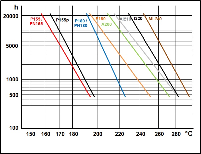
The line chart below is for technical comparison only and cannot be used to forecast lifetime of wound products (see also IEC 60172)

Thermal Stability in Hours [h] vs. Temperature in Degrees Celsius [°C]
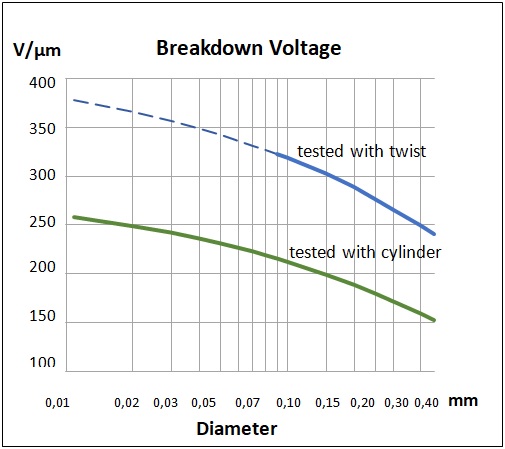
Average breakdown voltage at 20°C
|
|
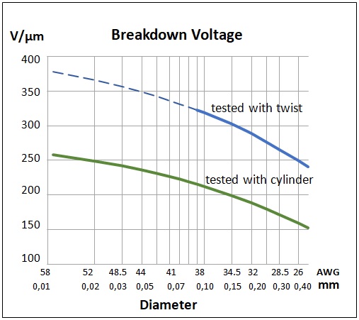
Calculation of Breakdown Voltage (Test acc. to IEC 60851-5 4.)
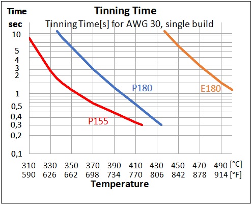
Solderability of different Wire Types
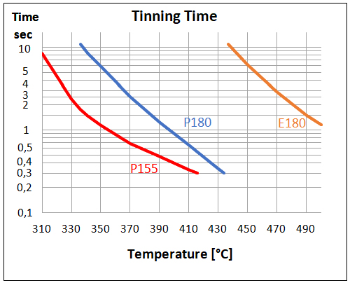
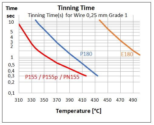
Tinning time [sec] for wire 0.25mm Grade 1 vs. Tin bath temp. [°C]
|
Product Code
|
P155 |
P180 |
G180 |
E180 |
A200 |
AI210 |
I220
|
ML240
|
|---|---|---|---|---|---|---|---|---|
| Product-Name | Polysol© 155 | Polysol© 180 | Estersol© 180 | Amidester© 200 | Amidester© 210 | |||
| General Description | mod. Polyurethane | mod. Polyurethane | mod. Polyurethane | Polyesterimide | Theic-mod. Polyesterimide | A200 + Polyamidimide | Polyamidimide | aromatic Polyimide |
| IEC (including the following standards) |
IEC 60317-20, IEC 60317-4 |
IEC 60317-51, IEC 60317-20 |
IEC 60317-51, IEC 60317-20 |
IEC 60317-23, IEC 60317-3, IEC 60317-8 |
IEC 60317-84, IEC 60317-8 |
IEC 60317-13 |
IEC 60317-57, IEC 60317-26 |
IEC 60317-46, IEC 60317-7 |
| NEMA (including the following standards) | MW 79, MW 2, MW 75 | MW 82, MW 79, MW 75 | MW 82, MW 79, MW 75 | MW 77, MW 5, MW 30 | MW 74, MW 5, MW 30 | MW 35, MW 73 | MW 81 | MW 16 |
| UL-approval | yes | yes | yes | yes | yes | yes | yes | yes |
| Diameters available | 0.010 - 0.50 mm | 0.010 - 0.50 mm | 0.010 - 0.50 mm | 0.010 - 0.50 mm | 0.010 - 0.50 mm | 0.015 - 0.50 mm | 0.015 - 0.50 mm | 0.015 - 0.50 mm |
| Properties | Very good solderability and high thermal properties. | Good solderability at 370°C and elevated thermal values. | Lubricant free, very low outgassing, good solderability at 370°C and elevated thermal values. | Solderable at high temperatures, high thermal properties and good chemical resistance. | Very high thermal properties and good chemical resistance. | Very high thermal properties and high mechanical resistance. | High thermal properties, good chemical resistance. | Excellent thermal properties, excellent chemical and high radiation resistance. |
| Applications | Small transformers, relays, solenoids, small motors, watch coils, transformers, instruments. | Automotive coils as relays and ignition coils, transformers and solenoids. | Closed relays and SMD components. | Small motors, small transformers, automotive coils. | Motors, small motors, transformers. | Motors, transformers. | Small motors, automotive sensors and solenoids, transformers. | Extreme loads and space applications. |
| Thermal values | ||||||||
| Temperature index 20.000 h acc. to IEC 60172 | 158°C | 192°C | 192°C | 195°C | 210°C | 212°C | 230°C | 245°C |
| Thermal stability chart [view] | ||||||||
| Cut through temperature | ||||||||
| 0.05mm: acc. to IEC 60851-6 4 | ≥ 200°C | ≥ 230°C | ≥ 230°C | ≥ 265°C | ≥ 320°C | ≥ 320°C | ≥ 350°C | ≥ 450°C |
| Elektrisola typical value | 225°C | 260°C | 260°C | 315°C | 350°C | 365°C | 390°C | 450°C |
| 0.25mm: acc. to IEC 60851-6 4 | ≥ 200°C | ≥ 230°C | ≥ 230°C | ≥ 265°C | ≥ 320°C | ≥ 320°C | ≥ 350°C | ≥ 450°C |
| Elektrisola typical value | 230°C | 265°C | 265°C | 325°C | 360°C | 380°C | 410°C | 500°C |
| Heat Shock | ||||||||
| 0.05mm: acc. to IEC 60851-6 3 | ≥ 175°C | ≥ 200°C | ≥ 200°C | ≥ 200°C | ≥ 220°C | ≥ 220°C | ≥ 240°C | ≥ 260°C |
| Elektrisola typical value | 190°C | 210°C | 210°C | 260°C | 230°C | 250°C | 250°C | 330°C |
| 0.25mm: acc. to IEC 60851-6 3 | ≥ 175°C | ≥ 200°C | ≥ 200°C | ≥ 200°C | ≥ 220°C | ≥ 220°C | ≥ 240°C | ≥ 260°C |
| Elektrisola typical value | 180°C | 200°C | 200°C | 250°C | 220°C | 240°C | 240°C | 320°C |
| Electrical values | ||||||||
| Low voltage continuity for Grade 1 wires | ||||||||
| 0.05mm: acc. to IEC 60851-5 1 | ≤ 40 | ≤ 40 | ≤ 40 | ≤ 40 | ≤ 40 | ≤ 40 | ≤ 40 | ≤ 40 |
| Elektrisola typical value | 0 | 0 | 0 | 0 | 0 | 0 | 0 | 0 |
| High voltage continuity for Grade 1 wires | ||||||||
| 0.05mm: Elektrisola typical value | 2 | 2 | 2 | 2 | 2 | 2 | 2 | 2 |
| 0.25mm: acc. to IEC 60851-5 2 | ≤ 10 | ≤ 10 | ≤ 10 | ≤ 10 | ≤ 10 | ≤ 10 | ≤ 10 | ≤ 10 |
| 0.25mm: Elektrisola typical value | 1 | 1 | 1 | 1 | 1 | 1 | 1 | 1 |
| Breakdown voltage acc. to IEC 60851-5 4 (at 20 °C, 35% humidity) | ||||||||
| 0.05mm: Elektrisola typical value | 220 V/µm | 220 V/µm | 220 V/µm | 220 V/µm | 220 V/µm | 210 V/µm | 210 V/µm | 210 V/µm |
| 0.25mm: Elektrisola typical value | 180 V/µm | 180 V/µm | 180 V/µm | 180 V/µm | 180 V/µm | 170 V/µm | 170 V/µm | 170 V/µm |
| Calculation method of break voltage [view] | ||||||||
| Decrease of breakdown voltage at elevated temperature for Grade 1 wires | ||||||||
| 0.05mm: Elektrisola typical value | 25% / 155°C | 20% / 180°C | 20% / 180°C | 20% / 200°C | 20% / 200°C | 20% / 220°C | 20% / 220°C | 15% / 240°C |
| 0.25mm: Elektrisola typical value | 25% / 155°C | 20% / 180°C | 20% / 180°C | 20% / 180°C | 20% / 200°C | 20% / 200°C | 20% / 220°C | 15% / 240°C |
| Mechanical values | ||||||||
| Elongation for Grade 1 wire | ||||||||
| 0.05mm: acc. to IEC 60851-3 Part 3 1 | ≥ 14% | ≥ 14% | ≥ 14% | ≥ 14% | ≥ 14% | ≥ 14% | ≥ 14% | ≥ 14% |
| 0.05mm: Elektrisola typical value | 23% | 23% | 23% | 23% | 23% | 23% | 23% | 23% |
| 0.25mm: acc. to IEC 60851-3 Part 3 1 | ≥ 25% | ≥ 25% | ≥ 25% | ≥ 25% | ≥ 25% | ≥ 25% | ≥ 25% | ≥ 25% |
| 0.25mm: Elektrisola typical value | 40% | 40% | 40% | 40% | 40% | 40% | 40% | 40% |
| Tensile strength for Grade 1 wires | ||||||||
| 0.05mm: Elektrisola typical value | 57 cN | 57 cN | 57 cN | 57 cN | 57 cN | 57 cN | 57 cN | 57 cN |
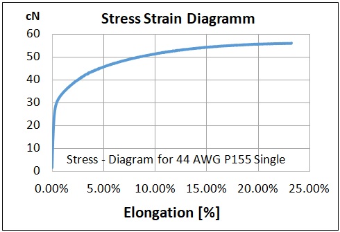
| 0.25mm: Elektrisola typical value | 1370 cN | 1370 cN | 1370 cN | 1370 cN | 1370 cN | 1370 cN | 1370 cN | 1370 cN |
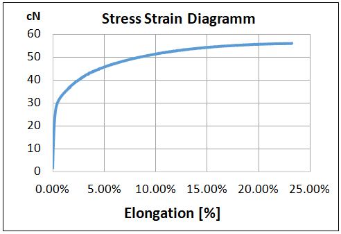
| Stress strain chart [view] | ||||||||
| Chemical compatibility | ||||||||
| Compatibility to standard solution | ||||||||
| Pencil Hardness acc. to IEC 60851-4 3 without treatment | ≥ H | ≥ H | ≥ H | ≥ H | ≥ H | ≥ H | ≥ H | ≥ H |
| Pencil Hardness acc. to IEC 60851-4 3 with treatment | ≥ H | ≥ H | ≥ H | ≥ H | ≥ 2B | ≥ H | ≥ H | ≥ HB |
| Decrease of breakdown voltage in % after treatment | 5% | 0% | 0% | 0% | 5% | 0% | 5% | 0% |
| RoHS laboratory analysis | view | view | view | view | view | view | view | |
| Solderablity | ||||||||
| Solderability for Grade 1 wires | ||||||||
| 0.05mm: max. acc. to IEC 60851-4 5 | 2.0s / 390°C | 3.0s / 390°C | 3.0s / 390°C | 3.0s / 470°C | not solderable | not solderable | not solderable | not solderable |
| Elektrisola typical value | 0.3s / 370°C | 1.8s / 370°C | 1.8s / 370°C | 1.8s / 470°C | ||||
| Elektrisola typical value | 0.2s / 390°C | 0.7s / 390°C | 0.7s / 390°C | |||||
| 0.25mm: max. acc. to IEC 60851-4 5 | 3.0s / 390°C | 3.0s / 390°C | 3.0s / 390°C | 3.0s / 470°C | not solderable | not solderable | not solderable | not solderable |
| Elektrisola typical value | 0.7s / 370°C | 2.8s / 370°C | 2.8s / 370°C | 2.8s / 470°C | ||||
| Elektrisola typical value | 0.5s / 390°C | 1.1s / 390°C | 1.1s / 390°C | |||||
| Solderability of different wire types chart [view] |
Asia
Enamelled Copper Wires acc. to IEC-Asia
IEC 60317 specifies different enamelled wire types. Test methods referred to are IEC 60851, which are also partially adopted by JIS.
Thermal Stability acc. to IEC 60172
The line chart below is for technical comparison only and cannot be used to forecast lifetime of wound products (see also IEC 60172)
Thermal Stability in Hours [h] vs. Temperature in Degrees Celsius [°C]
Average breakdown voltage at 20°C
|
|
|
Calculation of Breakdown Voltage (Test acc. to IEC 60851.5.4.2, cylinder) The Breakdown voltage depends mainly on the thickness of the insulation (see formula), but also on the bare wire diameter, the application temperature of the coil and the type of enamel.

Solderability of different Wire Types
Tinning time [sec] for wire 0.25mm Grade 1 vs. Tin bath temp. [°C]
|
Product Code
|
P155
|
PN155
|
P155p
|
P180
|
E180
|
A200
|
AI210
|
I220
|
ML240
|
|---|---|---|---|---|---|---|---|---|---|
| Product-Name | Polysol© 155 | Polysol-N© 155 | Polysol© 155p | Polysol© 180 | Estersol© 180 | Amidester© 200 | Amidester© 210 | ||
| General Description | mod. Polyurethane | mod. Polyurethane/ Polyamide overcoat | mod. Polyurethane | mod. Polyurethane | Polyesterimide | Theic-mod. Polyesterimide | A200 + Polyamidimide | Polyamidimide | aromatic Polyimide |
| IEC (including the following norms) | IEC 60317-20, IEC 60317-4 | IEC 60317-21, IEC 60317-19 | IEC 60317-20, IEC 60317-4 | IEC 60317-51, IEC 60317-20 | IEC 60317-23, IEC 60317-3, IEC 60317-8 | IEC 60317-84, IEC 60317-8 |
IEC 60317-13 | IEC 60317-57, IEC 60317-26 | IEC 60317-46, IEC 60317-7 |
| NEMA (including the following norms) | MW 79, MW 2, MW 75 | MW 80, MW 28 | MW 79, MW 2, MW 75 | MW 82, MW 79, MW 75 | MW 77, MW 5, MW 30 | MW 74, MW 5, MW 30 | MW 35, MW 73 | MW 81 | MW 16 |
| UL-approval | yes | yes | yes | yes | yes | yes | yes | yes | yes |
| Diameters available | 0.010 - 0.50 mm | 0.010 - 0.50 mm | 0.010 - 0.50 mm | 0.010 - 0.50 mm | 0.010 - 0.50 mm | 0.010 - 0.50 mm | 0.015 - 0.50 mm | 0.020 - 0.50 mm | 0.015 - 0.50 mm, ex USA |
| Properties | Very good solderability and high thermal properties. | Very good solderability with high thermal properties. | Very good solderability and high thermal properties, no elongation pinholes. | Good solderability at 370°C and elevated thermal values. | Solderable at high temperatures, high thermal properties and good chemical resistance. | Very high thermal properties and good chemical resistance. | Very high thermal properties and high mechanical resistance. | High thermal properties, good chemical resistance. | Excellent thermal properties, excellent chemical and high radiation resistance. |
| Applications | Small transformers, relays, solenoids, small motors, watch coils, transformers, instruments. | Appliance motors, encapsulated coils, solenoids, transformers, toroids. | Small transformers, timers, relays, small motors, solenoids, clock coils, watch coils, magnetic heads. | Automotive coils as relays and ignition coils, transformers and solenoids. | Small motors, small transformers, automotive coils. | Motors, small motors, transformers. | Motors, transformers. | Small motors, automotive sensors and solenoids, transformers. | Extreme loads and space applications. |
| Thermal values | |||||||||
| Temperature index 20.000 h acc. to IEC 60172 | 158°C | 158°C | 164°C | 192°C | 195°C | 210°C | 212°C | 230°C | 245°C |
| Thermal stability chart [view] | |||||||||
| Cut through temperature | |||||||||
| 0.05mm: acc. to IEC 60851-6 4 | ≥ 200°C | ≥ 200°C | ≥ 200°C | ≥ 230°C | ≥ 265°C | ≥ 320°C | ≥ 320°C | ≥ 350°C | ≥ 450°C |
| Elektrisola typical value | 225°C | 225°C | 225°C | 260°C | 315°C | 350°C | 365°C | 390°C | 450°C |
| 0.25mm: acc. to IEC 60851-6 4 | ≥ 200°C | ≥ 200°C | ≥ 200°C | ≥ 230°C | ≥ 265°C | ≥ 320°C | ≥ 350°C | ≥ 450°C | |
| Elektrisola typical value | 230°C | 230°C | 230°C | 265°C | 325°C | 360°C | 380°C | 410°C | 450°C |
| Heat Shock | |||||||||
| 0.05mm: acc. to IEC 60851-6 3 | ≥ 175°C | ≥ 175°C | ≥ 175°C | ≥ 200°C | ≥ 200°C | ≥ 220°C | ≥ 220°C | ≥ 240°C | ≥ 260°C |
| Elektrisola typical value | 190°C | 190°C | 190°C | 210°C | 260°C | 230°C | 250°C | 250°C | 300°C |
| 0.25mm: acc. to IEC 60851-6 3 | ≥ 175°C | ≥ 175°C | ≥ 175°C | ≥ 200°C | ≥ 200°C | ≥ 220°C | ≥ 220°C | ≥ 240°C | ≥ 260°C |
| Elektrisola typical value | 180°C | 180°C | 180°C | 200°C | 250°C | 220°C | 240°C | 240°C | 300°C |
| Electrical values | |||||||||
| Low voltage continuity for Grade 1 wires | |||||||||
| 0.05mm: acc. to IEC 60851-5 1 | ≤ 40 | ≤ 40 | ≤ 40 | ≤ 40 | ≤ 40 | ≤ 40 | ≤ 40 | ≤ 40 | ≤ 40 |
| Elektrisola typical value | 0 | 0 | 0 | 0 | 0 | 0 | 0 | 0 | 0 |
| High voltage continuity for Grade 1 wires | |||||||||
| 0.05mm: Elektrisola typical value | 2 | 2 | 2 | 2 | 2 | 2 | 2 | 2 | 2 |
| 0.25mm: acc. to IEC 60851-5 2 | ≤ 10 | ≤ 10 | ≤ 10 | ≤ 10 | ≤ 10 | ≤ 10 | ≤ 10 | ≤ 10 | ≤ 10 |
| Elektrisola typical value | 1 | 1 | 1 | 1 | 1 | 1 | 1 | 1 | 1 |
| Pinholes acc. to JIS C3003.6c | |||||||||
| with 0% elongation | good | good | very good | very good | very good | very good | very good | very good | very good |
| with 3% elongation | not good | not good | very good | very good | very good | good | very good | very good | very good |
| Breakdown voltage acc. to IEC 60851-5 4 (at 20 ?, 35% humidity) | |||||||||
| 0.05mm: Elektrisola typical value | 220 V/µm | 210 V/µm | 220 V/µm | 220 V/µm | 220 V/µm | 220 V/µm | 210 V/µm | 210 V/µm | 210 V/µm |
| 0.25mm: Elektrisola typical value | 180 V/µm | 150 V/µm | 180 V/µm | 180 V/µm | 180 V/µm | 180 V/µm | 170 V/µm | 170 V/µm | 170 V/µm |
| Decrease of breakdown voltage for Grade 1 wires | |||||||||
| 0.05mm: Elektrisola typical value | 25% / 155°C | 30% / 155°C | 20% / 180°C | 20% / 180°C | 20% / 200°C | 20% / 205°C | 20% / 205°C | 15% / 220°C | |
| 0.25mm: Elektrisola typical value | 25% / 155°C | 30% / 155°C | 25% / 155°C | 20% / 180°C | 20% / 180°C | 20% / 200°C | 20% / 205°C | 20% / 205°C | 15% / 220°C |
| Calculation method of break voltage [view] | |||||||||
| Mechanical values | |||||||||
| Elongation for Grade 1 wire | |||||||||
| 0.05mm: acc. to IEC 60851-3 Part 3 1 | ≥ 14% | ≥ 14% | ≥ 14% | ≥ 14% | ≥ 14% | ≥ 14% | ≥ 14% | ≥ 14% | ≥ 14% |
| Elektrisola typical value | 23% | 23% | 23% | 23% | 23% | 23% | 23% | 23% | 23% |
| 0.25mm: acc. to IEC 60851-3 Part 3 1 | ≥ 25% | ≥ 25% | ≥ 25% | ≥ 25% | ≥ 25% | ≥ 25% | ≥ 25% | ≥ 25% | ≥ 25% |
| Elektrisola typical value | 40% | 40% | 40% | 40% | 40% | 40% | 40% | 40% | 40% |
| Tensile strength for Grade 1 wires | |||||||||
| 0.05mm: Elektrisola typical value | 57 cN | 57 cN | 57 cN | 57 cN | 57 cN | 57 cN | 57 cN | 57 cN | 57 cN |
| 0.25mm: Elektrisola typical value | 1370 cN | 1370 cN | 1370 cN | 1370 cN | 1370 cN | 1370 cN | 1370 cN | 1370 cN | 1370 cN |
| Stress strain chart [view] | |||||||||
| Chemical compatibility | |||||||||
| Compatibility to standard solution | |||||||||
| Pencil Hardness acc. to IEC 60851-4 3 with treatment | 4H | 4H | 4H | 4H | 4H | 4H | 4H | 4H | 6H |
| Pencil Hardness acc. to IEC 60851-4 3 without treatment | 4H | 4H | 4H | 4H | 4H | 4H | 4H | 4H | 6H |
| Decrease of breakdown voltage in % after treatment | 5% | 5% | 5% | 0% | 0% | 5% | 0% | 5% | 0% |
| RoHS laboratory analysis | view | view | view | view | view | view | view | ||
| Solderability | |||||||||
| Solderability for Grade 1 wires | |||||||||
| 0.05mm: max. acc. to IEC 60851-4 5 | 2.0s / 390°C | 2.0s / 390°C | 2.0s / 390°C | 3.0s / 390°C | 3.0s / 470°C | not solderable | not solderable | not solderable | not solderable |
| Elektrisola typical value | 0.3s / 370°C | 0.3s / 370°C | 0.3s / 370°C | 1.8s / 370°C | 1.8s / 470°C | ||||
| Elektrisola typical value | 0.2s / 390°C | 0.2s / 390°C | 0.2s / 390°C | 0.7s / 390°C | |||||
| 0.25mm: max. acc. to IEC 60851-4 5 | 2.0s / 390°C | 2.0s / 390°C | 2.0s / 390°C | 3.0s / 390°C | 3.0s / 470°C | not solderable | not solderable | not solderable | not solderable |
| Elektrisola typical value | 0.7s / 370°C | 0.7s / 370°C | 0.7s / 370°C | 2.8s / 370°C | 2.8s / 470°C | ||||
| Elektrisola typical value | 0.5s / 390°C | 0.5s / 390°C | 0.5s / 390°C | 1.1s / 390°C | |||||
| Solderability of different wire types chart [view] |
America (inch)
Copper Magnet Wire acc. to NEMA MW 1000C (inch)
Thermal Stability acc. to IEC 60172
The line chart below is for technical comparison only and cannot be used to forecast lifetime of wound products (see also ASTM D2307)
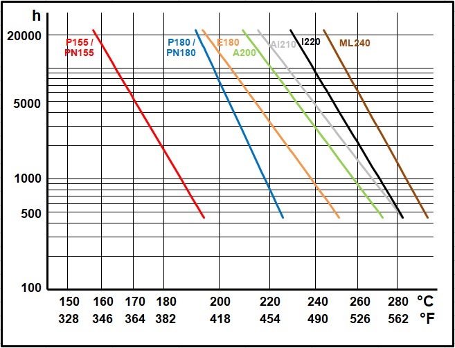
Thermal Stability in Hours [h] vs. Temperature in Degrees Celsius [°C] or Fahrenheit [°F]
Average breakdown voltage at 20°C
|
|
Calculation of Breakdown Voltage (Test acc. to IEC 60851.5.4.2, cylinder)
Solderability of different Wire Types
|
Product Code
|
P155
|
PN155
|
P180
|
E180
|
A200
|
AI210
|
I220
|
ML240
|
|---|---|---|---|---|---|---|---|---|
| Product-Name | Polysol© 155 | Polysol-N© 155 | Polysol© 180 | Estersol© 180 | Amidester© 200 | Amidester© 210 | ||
| General Description | mod. Polyurethane | mod. Polyurethane/ Polyamide overcoat | mod. Polyurethane | Polyesterimide | Theic-mod. Polyesterimide | A200 + Polyamidimide | Polyamidimide | aromatic Polyimide |
| NEMA (including the following norms) | MW 79, MW 2, MW 75 | MW 80, MW 28 | MW 82, MW 79, MW 75 | MW 77, MW 5, MW 30 | MW 74, MW 5, MW 30 | MW 35, MW 73 | MW 81 | MW 16 |
| IEC (including the following norms) | IEC 60317-20, IEC 60317-4 | IEC 60317-21, IEC 60317-19 | IEC 60317-51, IEC 60317-20 | IEC 60317-23, IEC 60317-3/8 | IEC 60317-84, IEC 60317-8 |
IEC 60317-13 | IEC 60317-57, IEC 60317-26 | IEC 60317-46, IEC 60317-7 |
| UL-approval | yes | yes | yes | yes | yes | yes | yes | yes |
| Diameters available | 56 - 24 AWG | 56 - 24 AWG | 56 - 24 AWG | 56 - 24 AWG | 56 - 24 AWG | 56 - 24 AWG | 52 - 24 AWG | 56 - 24 AWG |
| Properties | Very good solderability and high thermal properties. | Very good solderability with high thermal properties. | Good solderability at 370°C and elevated thermal values. | Solderable at high temperatures, high thermal properties and good chemical resistance. | Very high thermal properties and good chemical resistance. | Very high thermal properties and high mechanical resistance. | High thermal properties, good chemical resistance. | Excellent thermal properties, excellent chemical and high radiation resistance. |
| Applications | Small transformers, relays, solenoids, small motors, watch coils, transformers, instruments. | Appliance motors, encapsulated coils, solenoids, transformers, toroids. | Automotive coils as relays and ignition coils, transformers and solenoids. | Small motors, small transformers, automotive coils. | Motors, small motors, transformers. | Motors, transformers. | Small motors, automotive sensors and solenoids, transformers. | Extreme loads and space applications. |
| Thermal values | ||||||||
| Temperature index 20,000 h acc. to ASTM D 2307 | 158°C | 170°C | 192°C | 195°C | 210°C | 212°C | 230°C | 245°C |
| Thermal stability chart [view] | ||||||||
| Cut through temperature | ||||||||
| 44 AWG: acc. to NEMA MW1000, 3.50 | ≥ 200°C | ≥ 200°C | ≥ 225°C | ≥ 225°C | ≥ 300°C | ≥ 320°C | ≥ 350°C | ≥ 450°C |
| Elektrisola typical value | 225°C | 225°C | 260°C | 315°C | 350°C | 365°C | 390°C | 480°C |
| 30 AWG: acc. to NEMA MW1000, 3.50 | ≥ 200°C | ≥ 200°C | ≥ 225°C | ≥ 225°C | ≥ 300°C | ≥ 320°C | ≥ 350°C | ≥ 450°C |
| Elektrisola typical value | 230°C | 230°C | 265°C | 325°C | 360°C | 380°C | 410°C | 480°C |
| Heat Shock | ||||||||
| 44 AWG: acc. to NEMA MW1000, 3.5 | ≥ 175°C | ≥ 175°C | ≥ 200°C | ≥ 200°C | ≥ 220°C | ≥ 220°C | ≥ 240°C | ≥ 280°C |
| Elektrisola typical value | 190°C | 190°C | 210°C | 260°C | 230°C | 230°C | 250°C | 300°C |
| 30 AWG: acc. to NEMA MW1000, 3.5 | ≥ 175°C | ≥ 175°C | ≥ 200°C | ≥ 200°C | ≥ 220°C | ≥ 220°C | ≥ 240°C | ≥ 280°C |
| Elektrisola typical value | 180°C | 180°C | 200°C | 250°C | 220°C | 220°C | 240°C | 300°C |
| Electrical values | ||||||||
| Low voltage continuity acc. to NEMA MW 1000, 3.9.3 | ||||||||
| 44 AWG single: acc. to NEMA MW 1000, 3.9.3 | ≤ 25 | ≤ 25 | ≤ 25 | ≤ 25 | ≤ 25 | ≤ 25 | ≤ 25 | ≤ 25 |
| Elektrisola typical value | 0 | 0 | 0 | 0 | 0 | 0 | 0 | 0 |
| High voltage continuity acc. to NEMA MW 1000, 3.9.2 | ||||||||
| 44 AWG single: acc. to NEMA MW 1000, 3.9.2 | ≤ 15 | ≤ 15 | ≤ 15 | ≤ 15 | ≤ 15 | ≤ 15 | ≤ 15 | ≤ 15 |
| Elektrisola typical value | 2 | 2 | 2 | 2 | 2 | 2 | 2 | 2 |
| 30 AWG single: acc. to NEMA MW 1000, 3.9.2 | ≤ 15 | ≤ 15 | ≤ 15 | ≤ 15 | ≤ 15 | ≤ 15 | ≤ 15 | ≤ 15 |
| Elektrisola typical value | 1 | 1 | 1 | 1 | 1 | 1 | 1 | 1 |
| Breakdown voltage (at 20° C, 35% humidity) acc. to NEMA MW1000, 3.8.7 | ||||||||
| 44 AWG single: Elektrisola typical value | 9000 V/mil | 8700 V/mil | 9000 V/mil | 9000 V/mil | 9000 V/mil | 8700 V/mil | 8700 V/mil | 8700 V/mil |
| 30 AWG single: Elektrisola typical value | 6000 V/mil | 5800 V/mil | 6000 V/mil | 6000 V/mil | 6000 V/mil | 5800 V/mil | 5800 V/mil | |
| Decrease of breakdown voltage in % at elevated temperature, Elektrisola typical value for 44/30AWG, Single build | ||||||||
| 44 AWG single: Elektrisola typical value | 25% / 155°C | 30% / 155°C | 20% / 180°C | 20% / 180°C | 20% / 200°C | 20% / 205°C | 20% / 205°C | 15% / 220°C |
| 30 AWG single: Elektrisola typical value | 25% / 155°C | 30% / 155°C | 20% / 180°C | 20% / 180°C | 20% / 200°C | 20% / 205°C | 20% / 205°C | 15% / 220°C |
| Calculation method of break voltage [view] | ||||||||
| Mechanical values | ||||||||
| Elongation min. acc. to NEMA MW 1000, 3.4 for 44/30 AWG | ||||||||
| 44 AWG: acc. to NEMA MW 1000, 3.4 | ≥ 14% | ≥ 14% | ≥ 14% | ≥ 14% | ≥ 14% | ≥ 14% | ≥ 14% | ≥ 14% |
| Elektrisola typical value | 23% | 23% | 23% | 23% | 23% | 23% | 23% | 23% |
| 30 AWG: acc. to NEMA MW 1000, 3.4 | ≥ 25% | ≥ 25% | ≥ 25% | ≥ 25% | ≥ 25% | ≥ 25% | ≥ 25% | ≥ 25% |
| Elektrisola typical value | 40% | 40% | 40% | 40% | 40% | 40% | 40% | 40% |
| Tensile strength for Grade 1 wires | ||||||||
| 44 AWG: Elektrisola typical value | 57 cN | 57 cN | 57 cN | 57 cN | 57 cN | 57 cN | 57 cN | 57 cN |
| 30 AWG: Elektrisola typical value | 1370 cN | 1370 cN | 1370 cN | 1370 cN | 1370 cN | 1370 cN | 1370 cN | 1370 cN |
| Stress strain chart [view] | ||||||||
| Chemical compatibility | ||||||||
| Solubility per NEMA MW 1000, 3.51.1.1.3 | Pass | Pass | Pass | Pass | Pass | Pass | Pass | Pass |
| Compatibility to standard solution | ||||||||
| Decrease of breakdown voltage in % after treatment | 5% | 5% | 5% | 5% | 5% | 0% | 0% | 5% |
| RoHS laboratory analysis | view | view | view | view | view | view | ||
| Solderability | ||||||||
| Solderability acc. to. NEMA MW 1000 3.13.1.1 max. seconds at °C for 44/30 AWG | ||||||||
| 44 AWG: acc. to NEMA MW 1000 3.13 | 2.5s / 390°C | 2.5s / 390°C | 2.5s / 390°C | 4.0s / 470°C | not solderable | not solderable | not solderable | not solderable |
| Elektrisola typical value | 0.3s / 370°C | 0.3s / 370°C | 1.5s / 370°C | 1.8s / 470°C | ||||
| Elektrisola typical value | 0.2s / 390°C | 0.2s / 390°C | 0.7s / 390°C | |||||
| 30 AWG: acc. to NEMA MW 1000 3.13 | 3.5s / 390°C | 3.5s / 390°C | 3.5s / 390°C | 5.0s / 470°C | not solderable | not solderable | not solderable | not solderable |
| Elektrisola typical value | 0.7s / 370°C | 0.7s / 370°C | 2.8s / 370°C | 2.8s / 470°C | ||||
| Elektrisola typical value | 0.5s / 390°C | 0.5s / 390°C | 1.1s / 390°C | |||||
| Solderability of different wire types chart [view] |
America (metric)
Copper Magnet Wire acc. to NEMA MW 1000C (metric)
Thermal Stability acc. to IEC 60172
The line chart below is for technical comparison only and cannot be used to forecast lifetime of wound products (see also ASTM D2307)
Thermal Stability in Hours [h] vs. Temperature in Degrees Celsius [°C] or Fahrenheit [°F]
Average breakdown voltage at 20°C
|
|
|
Calculation of Breakdown Voltage (Test acc. to IEC 60851.5.4.2, cylinder)
Solderability of different Wire Types
|
Product Code
|
P155
|
PN155
|
P180
|
E180
|
A200
|
AI210
|
I220
|
ML240
|
|---|---|---|---|---|---|---|---|---|
| Product-Name | Polysol© 155 | Polysol-N© 155 | Polysol© 180 | Estersol© 180 | Amidester© 200 | Amidester© 210 | ||
| General Description | mod. Polyurethane | mod. Polyurethane/ Polyamide overcoat | mod. Polyurethane | Polyesterimide | Theic-mod. Polyesterimide | A200 + Polyamidimide | Polyamidimide | aromatic Polyimide |
| NEMA (including the following norms) | MW 79, MW 2, MW 75 | MW 80, MW 28 | MW 82, MW 79, MW 75 | MW 77, MW 5, MW 30 | MW 74, MW 5, MW 30 | MW 35, MW 73 | MW 81 | MW 16 |
| IEC (including the following norms) | IEC 60317-20, IEC 60317-4 | IEC 60317-21, IEC 60317-19 | IEC 60317-51, IEC 60317-20 | IEC 60317-23, IEC 60317-3/8 | IEC 60317-84, IEC 60317-8 |
IEC 60317-13 | IEC 60317-57, IEC 60317-26 | IEC 60317-46, IEC 60317-7 |
| UL-approval | yes | yes | yes | yes | yes | yes | yes | yes |
| Diameters available | 0.010 - 0.50 mm | 0.010 - 0.50 mm | 0.010 - 0.50 mm | 0.010 - 0.50 mm | 0.010 - 0.50 mm | 0.015 - 0.50 mm | 0.020 - 0.50 mm | 0.015 - 0.50 mm, ex USA |
| Properties | Very good solderability and high thermal properties. | Very good solderability with high thermal properties. | Good solderability at 370°C and elevated thermal values. | Solderable at high temperatures, high thermal properties and good chemical resistance. | Very high thermal properties and good chemical resistance. | Very high thermal properties and high mechanical resistance. | High thermal properties, good chemical resistance. | Excellent thermal properties, excellent chemical and high radiation resistance. |
| Applications | Small transformers, relays, solenoids, small motors, watch coils, transformers, instruments. | Appliance motors, encapsulated coils, solenoids, transformers, toroids. | Automotive coils as relays and ignition coils, transformers and solenoids. | Small motors, small transformers, automotive coils. | Motors, small motors, transformers. | Motors, transformers. | Small motors, automotive sensors and solenoids, transformers. | Extreme loads and space applications. |
| Thermal values | ||||||||
| Temperature index 20,000 h acc. to ASTM D 2307 | 158°C | 158°C | 192°C | 195°C | 210°C | 212°C | 230°C | 245°C |
| Thermal stability chart [view] | ||||||||
| Cut through temperature | ||||||||
| 44 AWG: acc. to NEMA MW1000, 3.50 | ≥ 200°C | ≥ 200°C | ≥ 225°C | ≥ 225°C | ≥ 300°C | ≥ 320°C | ≥ 350°C | ≥ 450°C |
| Elektrisola typical value | 225°C | 225°C | 260°C | 315°C | 350°C | 365°C | 390°C | 480°C |
| 30 AWG: acc. to NEMA MW1000, 3.50 | ≥ 200°C | ≥ 200°C | ≥ 225°C | ≥ 225°C | ≥ 300°C | ≥ 320°C | ≥ 350°C | ≥ 450°C |
| Elektrisola typical value | 230°C | 230°C | 265°C | 325°C | 360°C | 380°C | 410°C | 480°C |
| Heat Shock | ||||||||
| 44 AWG: acc. to NEMA MW1000, 3.5 | ≥ 175°C | ≥ 175°C | ≥ 200°C | ≥ 200°C | ≥ 220°C | ≥ 220°C | ≥ 240°C | ≥ 280°C |
| Elektrisola typical value | 190°C | 190°C | 210°C | 260°C | 230°C | 230°C | 250°C | 300°C |
| 30 AWG: acc. to NEMA MW1000, 3.5 | ≥ 175°C | ≥ 175°C | ≥ 200°C | ≥ 200°C | ≥ 220°C | ≥ 220°C | ≥ 240°C | ≥ 250°C |
| Elektrisola typical value | 180°C | 180°C | 200°C | 250°C | 220°C | 220°C | 240°C | 300°C |
| Electrical values | ||||||||
| Low voltage continuity acc. to NEMA MW 1000, 3.9.3 | ||||||||
| 44 AWG single: acc. to NEMA MW 1000, 3.9.3 | ≤ 15 | ≤ 15 | ≤ 15 | ≤ 15 | ≤ 15 | ≤ 15 | ≤ 15 | ≤ 15 |
| Elektrisola typical value | 0 | 0 | 0 | 0 | 0 | 0 | 0 | 0 |
| High voltage continuity acc. to NEMA MW 1000, 3.9.2 | ||||||||
| 44 AWG single: acc. to NEMA MW 1000, 3.9.2 | ≤ 15 | ≤ 15 | ≤ 15 | ≤ 15 | ≤ 15 | ≤ 15 | ≤ 15 | ≤ 15 |
| Elektrisola typical value | 2 | 2 | 2 | 2 | 2 | 2 | 2 | 2 |
| 30 AWG single: acc. to NEMA MW1000, 3.9.2 | ≤ 15 | ≤ 15 | ≤ 15 | ≤ 15 | ≤ 15 | ≤ 15 | ≤ 15 | ≤ 15 |
| Elektrisola typical value | 1 | 1 | 1 | 1 | 1 | 1 | 1 | 1 |
| Breakdown voltage (at 20° C, 35% humidity) acc. to NEMA MW1000, 3.8.7 | ||||||||
| 44 AWG single: Elektrisola typical value | 9000 V/mil | 8700 V/mil | 9000 V/mil | 9000 V/mil | 9000 V/mil | 8700 V/mil | 8700 V/mil | 8700 V/mil |
| 30 AWG single: Elektrisola typical value | 6000 V/mil | 5800 V/mil | 6000 V/mil | 6000 V/mil | 6000 V/mil | 5800 V/mil | 5800 V/mil | |
| Decrease of breakdown voltage in % at elevated temperature, Elektrisola typical value for 44/30AWG, Single build | ||||||||
| 44 AWG single: Elektrisola typical value | 25% / 155°C | 30% / 155°C | 20% / 180°C | 20% / 180°C | 20% / 200°C | 20% / 205°C | 20% / 205°C | 15% / 220°C |
| 30 AWG single: Elektrisola typical value | 25% / 155°C | 30% / 155°C | 20% / 180°C | 20% / 180°C | 20% / 200°C | 20% / 205°C | 20% / 205°C | 15% / 220°C |
| Calculation method of break voltage [view] | ||||||||
| Mechanical values | ||||||||
| Elongation min. acc. to NEMA MW 1000, 3.4 for 44/30 AWG | ||||||||
| 44 AWG: acc. to NEMA MW 1000, 3.4 | ≥ 14% | ≥ 14% | ≥ 14% | ≥ 14% | ≥ 14% | ≥ 14% | ≥ 14% | ≥ 14% |
| Elektrisola typical value | 23% | 23% | 23% | 23% | 23% | 23% | 23% | 23% |
| 30 AWG: acc. to NEMA MW 1000, 3.4 | ≥ 25% | ≥ 25% | ≥ 25% | ≥ 25% | ≥ 25% | ≥ 25% | ≥ 25% | ≥ 25% |
| Elektrisola typical value | 40% | 40% | 40% | 40% | 40% | 40% | 40% | 40% |
| Tensile strength for Grade 1 wires | ||||||||
| 44 AWG: Elektrisola typical value | 57 cN | 57 cN | 57 cN | 57 cN | 57 cN | 57 cN | 57 cN | 57 cN |
| 30 AWG: Elektrisola typical value | 1370 cN | 1370 cN | 1370 cN | 1370 cN | 1370 cN | 1370 cN | 1370 cN | 1370 cN |
| Stress strain chart [view] | ||||||||
| Chemical compatibility | ||||||||
| Solubility per NEMA MW 1000, 3.51.1.1.3 | Pass | Pass | Pass | Pass | Pass | Pass | Pass | Pass |
| Compatibility to standard solution | ||||||||
| Decrease of breakdown voltage in % after treatment | 5% | 5% | 0% | 0% | 5% | 0% | 5% | 0% |
| RoHS laboratory analysis | view | view | view | view | view | view | ||
| Solderability | ||||||||
| Solderability acc. to. NEMA MW 1000 3.13.1.1 max. seconds at °C for 44/30 AWG | ||||||||
| 44 AWG: acc. to NEMA MW 1000 3.13 | 4.0s / 390°C | 4.0s / 390°C | 4.0s / 390°C | 4.0s / 470°C | not solderable | not solderable | not solderable | not solderable |
| Elektrisola typical value | 0.3s / 370°C | 0.3s / 370°C | 1.5s / 370°C | 1.8s / 470°C | ||||
| Elektrisola typical value | 0.2s / 390°C | 0.2s / 390°C | 0.7s / 390°C | |||||
| 30 AWG: acc. to NEMA MW 1000 3.13 | 5.0s / 390°C | 5.0s / 390°C | 5.0s / 390°C | 5.0s / 470°C | not solderable | not solderable | not solderable | not solderable |
| Elektrisola typical value | 0.7s / 370°C | 0.7s / 370°C | 2.8s / 370°C | 2.8s / 470°C | ||||
| Elektrisola typical value | 0.5s / 390°C | 0.5s / 390°C | 1.1s / 390°C | |||||
| Solderability of different wire types chart [view] |
SB Technical Data
Self Bonding Technical Data
Tolerances and Technical Data by Size
Europe / Asia IEC 60317
Technical Data for Selfbonding Copper Wire by Size acc. to IEC 60317
| Minimum coat thickness and maximum overall diameter | |||||||||||||||||||
|---|---|---|---|---|---|---|---|---|---|---|---|---|---|---|---|---|---|---|---|
| Conductor (Bare Wire) |
Grade 1B | Grade 2B | Elongation acc to IEC |
Resistance at 20 °C | Breakdown Voltage acc to IEC ** |
1 kg of enamelled wire length approx. | Filling Factor number of enamelled wires/cm² |
Tension | |||||||||||
| Nominal Diameter | Tolerance | Section | min inc. base coat |
min inc. bond coat |
max o.d. | min inc. base coat |
min inc. bond coat |
max o.d. | min | nom | min | max | Grade 1B | Grade 2B | Grade 1B | Grade 2B | Grade 1B | Grade 2B | max |
| [mm] | [mm] | [mm²] | [mm] | [mm] | [mm] | [mm] | [mm] | [mm] | [%] | [Ohm/m] | [Ohm/m] | [Ohm/m] | min. [V] | min. [V] | [km] | [km] | [n] | [n] | [cN] |
| 0.010 | * | 0.000078540 | 0.0013 | 0.0008 | 0.0133 | 3 | 217.65 | 195.88 | 239.41 | 70 | 125 | 1306 | 715995 | 1.4 | |||||
| 0.012 | * | 0.000113097 | 0.0013 | 0.0008 | 0.0160 | 3 | 151.14 | 136.03 | 166.26 | 80 | 150 | 912.3 | 509852 | 2.0 | |||||
| 0.014 | * | 0.000153938 | 0.0016 | 0.0010 | 0.0190 | 4 | 111.04 | 99.94 | 122.15 | 90 | 175 | 666.3 | 364483 | 2.5 | |||||
| 0.016 | * | 0.000201062 | 0.0016 | 0.001 | 0.022 | 0.004 | 0.001 | 0.025 | 5 | 85.02 | 76.52 | 93.52 | 100 | 200 | 510.6 | 477.3 | 280237 | 212719 | 3.2 |
| 0.018 | * | 0.000254469 | 0.0018 | 0.001 | 0.024 | 0.004 | 0.001 | 0.027 | 5 | 67.18 | 60.46 | 73.89 | 110 | 225 | 406.8 | 384.2 | 230156 | 180417 | 3.9 |
| 0.019 | * | 0.000283529 | 0.0019 | 0.001 | 0.025 | 0.004 | 0.001 | 0.028 | 6 | 60.29 | 54.26 | 66.32 | 115 | 240 | 366.4 | 347.5 | 210006 | 166957 | 4.3 |
| 0.020 | * | 0.000314159 | 0.002 | 0.002 | 0.026 | 0.004 | 0.002 | 0.029 | 6 | 54.41 | 48.97 | 59.85 | 120 | 250 | 328.9 | 314.7 | 184773 | 152705 | 4.7 |
| 0.021 | * | 0.000346361 | 0.002 | 0.002 | 0.029 | 0.004 | 0.002 | 0.031 | 6 | 49.35 | 44.42 | 54.29 | 125 | 265 | 294.7 | 284.8 | 158413 | 137316 | 5.1 |
| 0.022 | * | 0.000380133 | 0.002 | 0.002 | 0.030 | 0.005 | 0.002 | 0.033 | 6 | 44.97 | 40.47 | 49.47 | 130 | 275 | 269.7 | 256.9 | 147300 | 120169 | 5.5 |
| 0.023 | * | 0.000415476 | 0.002 | 0.002 | 0.031 | 0.005 | 0.002 | 0.034 | 7 | 41.14 | 37.03 | 45.26 | 145 | 290 | 247.8 | 236.6 | 137316 | 112776 | 6.0 |
| 0.024 | * | 0.000452389 | 0.002 | 0.002 | 0.032 | 0.005 | 0.002 | 0.035 | 7 | 37.79 | 34.01 | 41.56 | 145 | 290 | 228.4 | 218.5 | 128314 | 106045 | 6.5 |
| 0.025 | * | 0.000490874 | 0.003 | 0.002 | 0.034 | 0.005 | 0.002 | 0.037 | 7 | 34.82 | 31.34 | 38.31 | 150 | 300 | 208.3 | 201.0 | 112776 | 97024 | 7.0 |
| 0.027 | * | 0.000572555 | 0.003 | 0.002 | 0.037 | 0.005 | 0.002 | 0.040 | 7 | 29.86 | 26.87 | 32.84 | 165 | 315 | 178.7 | 173.0 | 97024 | 84356 | 8.0 |
| 0.028 | * | 0.000615752 | 0.003 | 0.003 | 0.038 | 0.006 | 0.003 | 0.042 | 7 | 27.76 | 24.99 | 30.54 | 170 | 325 | 165.7 | 158.5 | 89107 | 74016 | 8.5 |
| 0.030 | * | 0.000706858 | 0.003 | 0.003 | 0.042 | 0.006 | 0.003 | 0.044 | 8 | 24.18 | 21.76 | 26.60 | 180 | 350 | 143.7 | 139.4 | 75926 | 67053 | 9.6 |
| 0.032 | * | 0.000804248 | 0.003 | 0.003 | 0.044 | 0.007 | 0.003 | 0.048 | 8 | 21.25 | 19.13 | 23.38 | 190 | 375 | 127.1 | 121.5 | 68699 | 57029 | 10.8 |
| 0.034 | * | 0.00090792 | 0.003 | 0.003 | 0.047 | 0.007 | 0.003 | 0.052 | 8 | 18.83 | 17.133 | 20.522 | 210 | 400 | 112.7 | 107.4 | 61029 | 50123 | 12.0 |
| 0.036 | * | 0.00101788 | 0.004 | 0.003 | 0.050 | 0.008 | 0.003 | 0.055 | 8 | 16.79 | 15.282 | 18.305 | 225 | 425 | 100.1 | 95.70 | 53409 | 44399 | 13.2 |
| 0.038 | * | 0.001134 | 0.004 | 0.003 | 0.052 | 0.008 | 0.003 | 0.057 | 10 | 15.07 | 13.716 | 16.429 | 240 | 450 | 90.29 | 86.56 | 49095 | 41112 | 14.5 |
| 0.040 | * | 0.001257 | 0.004 | 0.003 | 0.055 | 0.008 | 0.003 | 0.060 | 10 | 13.60 | 12.379 | 14.827 | 250 | 475 | 81.50 | 78.30 | 44399 | 37491 | 15.9 |
| 0.043 | * | 0.001452 | 0.004 | 0.003 | 0.059 | 0.009 | 0.003 | 0.065 | 12 | 11.77 | 10.712 | 12.831 | 265 | 520 | 70.73 | 67.59 | 38880 | 32079 | 18.0 |
| 0.045 | * | 0.001590 | 0.005 | 0.003 | 0.062 | 0.009 | 0.003 | 0.068 | 12 | 10.75 | 9.781 | 11.715 | 275 | 550 | 64.36 | 61.86 | 34929 | 29564 | 19.4 |
| 0.048 | * | 0.001810 | 0.005 | 0.003 | 0.067 | 0.010 | 0.003 | 0.073 | 14 | 9.447 | 8.596 | 10.297 | 290 | 580 | 56.48 | 54.21 | 30533 | 25726 | 21.7 |
| 0.050 | * | 0.001963 | 0.005 | 0.003 | 0.068 | 0.010 | 0.003 | 0.074 | 14 | 8.706 | 7.922 | 9.489 | 300 | 600 | 52.45 | 50.45 | 29096 | 24611 | 23.2 |
| 0.053 | * | 0.002206 | 0.005 | 0.003 | 0.072 | 0.010 | 0.003 | 0.078 | 15 | 7.748 | 7.051 | 8.446 | 315 | 625 | 46.76 | 45.08 | 26114 | 22277 | 25.6 |
| 0.056 | * | 0.002463 | 0.006 | 0.003 | 0.075 | 0.011 | 0.003 | 0.082 | 15 | 6.940 | 6.316 | 7.565 | 325 | 650 | 41.95 | 40.40 | 23568 | 19994 | 28.2 |
| 0.060 | * | 0.002827 | 0.006 | 0.003 | 0.081 | 0.011 | 0.003 | 0.088 | 16 | 6.046 | 5.502 | 6.590 | 355 | 680 | 36.55 | 35.29 | 20530 | 17601 | 31.7 |
| 0.063 | * | 0.003117 | 0.006 | 0.005 | 0.085 | 0.012 | 0.005 | 0.092 | 16 | 5.484 | 4.990 | 5.977 | 375 | 700 | 33.01 | 31.83 | 18272 | 15614 | 34.4 |
| 0.067 | ± 0.003 | 0.003526 | 0.007 | 0.005 | 0.090 | 0.012 | 0.005 | 0.098 | 17 | 4.848 | 4.412 | 5.285 | 400 | 700 | 29.19 | 28.21 | 16173 | 13946 | 38 |
| 0.070 | ± 0.003 | 0.003848 | 0.007 | 0.005 | 0.093 | 0.012 | 0.005 | 0.100 | 17 | 4.442 | 4.042 | 4.842 | 425 | 700 | 26.85 | 26.06 | 15083 | 13210 | 41 |
| 0.071 | ± 0.003 | 0.003959 | 0.007 | 0.005 | 0.094 | 0.012 | 0.005 | 0.101 | 17 | 4.318 | 3.929 | 4.706 | 425 | 700 | 26.13 | 25.37 | 14745 | 12932 | 42 |
| 0.075 | ± 0.003 | 0.004418 | 0.007 | 0.005 | 0.100 | 0.013 | 0.005 | 0.106 | 17 | 3.869 | 3.547 | 4.235 | 425 | 765 | 23.41 | 22.77 | 13210 | 11665 | 46 |
| 0.080 | ± 0.003 | 0.005027 | 0.007 | 0.005 | 0.105 | 0.014 | 0.005 | 0.112 | 17 | 3.401 | 3.133 | 3.703 | 425 | 850 | 20.69 | 20.07 | 11903 | 10376 | 52 |
| 0.085 | ± 0.003 | 0.005675 | 0.008 | 0.005 | 0.112 | 0.015 | 0.005 | 0.119 | 18 | 3.012 | 2.787 | 3.265 | 465 | 875 | 18.30 | 17.78 | 10475 | 9206 | 57 |
| 0.090 | ± 0.003 | 0.006362 | 0.008 | 0.005 | 0.117 | 0.015 | 0.005 | 0.125 | 18 | 2.687 | 2.495 | 2.900 | 500 | 900 | 16.40 | 15.93 | 9544 | 8365 | 63 |
| 0.095 | ± 0.003 | 0.007088 | 0.008 | 0.005 | 0.123 | 0.016 | 0.005 | 0.131 | 19 | 2.412 | 2.247 | 2.594 | 500 | 925 | 14.75 | 14.33 | 8657 | 7572 | 69 |
| 0.100 | ± 0.003 | 0.007854 | 0.008 | 0.005 | 0.129 | 0.016 | 0.005 | 0.137 | 19 | 2.176 | 2.034 | 2.333 | 500 | 950 | 13.34 | 12.97 | 7888 | 6940 | 75 |
| 0.106 | ± 0.003 | 0.008825 | 0.008 | 0.005 | 0.136 | 0.017 | 0.005 | 0.145 | 20 | 1.937 | 1.816 | 2.069 | 1200 | 2650 | 11.90 | 11.56 | 7104 | 6198 | 83 |
| 0.110 | ± 0.003 | 0.009503 | 0.009 | 0.008 | 0.141 | 0.017 | 0.008 | 0.150 | 20 | 1.799 | 1.690 | 1.917 | 1300 | 2700 | 10.99 | 10.70 | 6431 | 5687 | 88 |
| 0.112 | ± 0.003 | 0.009852 | 0.009 | 0.008 | 0.143 | 0.017 | 0.008 | 0.152 | 20 | 1.735 | 1.632 | 1.848 | 1300 | 2700 | 10.62 | 10.34 | 6244 | 5531 | 91 |
| 0.118 | ± 0.003 | 0.010936 | 0.010 | 0.009 | 0.150 | 0.019 | 0.009 | 0.159 | 20 | 1.563 | 1.474 | 1.660 | 1400 | 2750 | 9.558 | 9.310 | 5608 | 4966 | 99 |
| 0.120 | ± 0.003 | 0.011310 | 0.010 | 0.009 | 0.153 | 0.019 | 0.009 | 0.163 | 20 | 1.511 | 1.426 | 1.604 | 1500 | 2800 | 9.240 | 8.992 | 5418 | 4776 | 102 |
| 0.125 | ± 0.003 | 0.012272 | 0.010 | 0.009 | 0.158 | 0.019 | 0.009 | 0.168 | 20 | 1.393 | 1.317 | 1.475 | 1500 | 2800 | 8.541 | 8.321 | 5065 | 4483 | 110 |
| 0.130 | ± 0.003 | 0.013273 | 0.011 | 0.010 | 0.165 | 0.021 | 0.010 | 0.175 | 21 | 1.288 | 1.220 | 1.361 | 1550 | 2900 | 7.877 | 7.671 | 4626 | 4092 | 118 |
| 0.132 | ± 0.003 | 0.013685 | 0.011 | 0.010 | 0.167 | 0.021 | 0.010 | 0.177 | 21 | 1.249 | 1.184 | 1.319 | 1550 | 2900 | 7.648 | 7.452 | 4511 | 3996 | 121 |
| 0.140 | ± 0.003 | 0.015394 | 0.011 | 0.010 | 0.175 | 0.021 | 0.010 | 0.186 | 21 | 1.110 | 1.055 | 1.170 | 1600 | 3000 | 6.827 | 6.654 | 4092 | 3624 | 133 |
| 0.150 | ± 0.003 | 0.017671 | 0.012 | 0.010 | 0.186 | 0.023 | 0.010 | 0.197 | 22 | 0.9673 | 0.9219 | 1.0159 | 1650 | 3100 | 5.961 | 5.814 | 3604 | 3199 | 150 |
| 0.160 | ± 0.003 | 0.020106 | 0.012 | 0.010 | 0.197 | 0.023 | 0.010 | 0.209 | 22 | 0.8502 | 0.8122 | 0.8906 | 1700 | 3200 | 5.254 | 5.128 | 3216 | 2858 | 168 |
| 0.170 | ± 0.003 | 0.022698 | 0.013 | 0.010 | 0.210 | 0.025 | 0.010 | 0.221 | 23 | 0.7531 | 0.7211 | 0.7871 | 1700 | 3250 | 4.653 | 4.548 | 2844 | 2545 | 186 |
| 0.180 | ± 0.003 | 0.025447 | 0.013 | 0.010 | 0.220 | 0.025 | 0.010 | 0.233 | 23 | 0.6718 | 0.6444 | 0.7007 | 1700 | 3300 | 4.165 | 4.068 | 2582 | 2302 | 206 |
| 0.190 | ± 0.003 | 0.028353 | 0.014 | 0.011 | 0.233 | 0.027 | 0.011 | 0.245 | 24 | 0.6029 | 0.5794 | 0.6278 | 1750 | 3400 | 3.733 | 3.651 | 2302 | 2065 | 226 |
| 0.200 | ± 0.003 | 0.031416 | 0.014 | 0.011 | 0.243 | 0.027 | 0.011 | 0.256 | 24 | 0.5441 | 0.5237 | 0.5657 | 1800 | 3500 | 3.379 | 3.306 | 2109 | 1893 | 247 |
| 0.212 | ± 0.003 | 0.035299 | 0.015 | 0.012 | 0.258 | 0.029 | 0.012 | 0.272 | 24 | 0.4843 | 0.4669 | 0.5026 | 1850 | 3600 | 3.005 | 2.939 | 1870 | 1676 | 274 |
| 0.224 | ± 0.003 | 0.039408 | 0.015 | 0.012 | 0.270 | 0.029 | 0.012 | 0.284 | 24 | 0.4338 | 0.4188 | 0.4495 | 1900 | 3700 | 2.700 | 2.644 | 1702 | 1533 | 302 |
| 0.236 | ± 0.004 | 0.043744 | 0.017 | 0.013 | 0.286 | 0.032 | 0.013 | 0.302 | 25 | 0.3908 | 0.3747 | 0.4079 | 2000 | 3800 | 2.427 | 2.374 | 1516 | 1359 | 331 |
| 0.250 | ± 0.004 | 0.049087 | 0.017 | 0.013 | 0.300 | 0.032 | 0.013 | 0.316 | 25 | 0.3482 | 0.3345 | 0.3628 | 2100 | 3900 | 2.170 | 2.125 | 1373 | 1237 | 366 |
| 0.265 | ± 0.004 | 0.055155 | 0.018 | 0.013 | 0.316 | 0.033 | 0.013 | 0.333 | 26 | 0.3099 | 0.2982 | 0.3223 | 2150 | 3950 | 1.934 | 1.896 | 1233 | 1114 | 406 |
| 0.280 | ± 0.004 | 0.061575 | 0.018 | 0.013 | 0.331 | 0.033 | 0.013 | 0.348 | 26 | 0.2776 | 0.2676 | 0.2882 | 2200 | 4000 | 1.737 | 1.705 | 1121 | 1017 | 448 |
| 0.300 | ± 0.004 | 0.070686 | 0.019 | 0.014 | 0.354 | 0.035 | 0.014 | 0.372 | 26 | 0.2418 | 0.2335 | 0.2506 | 2200 | 4050 | 1.514 | 1.486 | 979 | 889 | 507 |
| 0.315 | ± 0.004 | 0.077931 | 0.019 | 0.014 | 0.369 | 0.035 | 0.014 | 0.387 | 26 | 0.2193 | 0.2121 | 0.2270 | 2200 | 4100 | 1.376 | 1.352 | 899 | 819 | 553 |
| 0.335 | ± 0.004 | 0.088141 | 0.020 | 0.015 | 0.393 | 0.038 | 0.015 | 0.412 | 27 | 0.1939 | 0.1878 | 0.2004 | 2250 | 4200 | 1.217 | 1.195 | 793 | 722 | 618 |
| 0.355 | ± 0.004 | 0.098980 | 0.020 | 0.015 | 0.413 | 0.038 | 0.015 | 0.432 | 27 | 0.1727 | 0.1674 | 0.1782 | 2300 | 4300 | 1.086 | 1.068 | 716 | 655 | 687 |
| 0.375 | ± 0.005 | 0.110447 | 0.021 | 0.016 | 0.436 | 0.040 | 0.016 | 0.456 | 27 | 0.1548 | 0.1494 | 0.1604 | 2300 | 4350 | 0.974 | 0.957 | 642 | 587 | 759 |
| 0.400 | ± 0.005 | 0.125664 | 0.021 | 0.016 | 0.461 | 0.040 | 0.016 | 0.481 | 27 | 0.1360 | 0.1316 | 0.1407 | 2300 | 4400 | 0.858 | 0.844 | 573 | 526 | 854 |
| 0.425 | ± 0.005 | 0.141863 | 0.022 | 0.016 | 0.489 | 0.042 | 0.016 | 0.511 | 28 | 0.1205 | 0.1167 | 0.1244 | 2300 | 4400 | 0.761 | 0.749 | 510 | 468 | 954 |
| 0.450 | ± 0.005 | 0.159043 | 0.022 | 0.016 | 0.514 | 0.042 | 0.016 | 0.536 | 28 | 0.1075 | 0.1042 | 0.1109 | 2300 | 4400 | 0.680 | 0.670 | 460 | 424 | 1060 |
| 0.475 | ± 0.005 | 0.177205 | 0.024 | 0.017 | 0.543 | 0.045 | 0.017 | 0.565 | 28 | 0.09646 | 0.09366 | 0.09938 | 2350 | 4500 | 0.610 | 0.601 | 412 | 380 | 1170 |
| 0.500 | ± 0.005 | 0.196350 | 0.024 | 0.017 | 0.568 | 0.045 | 0.017 | 0.590 | 28 | 0.08706 | 0.08462 | 0.08959 | 2400 | 4600 | 0.551 | 0.544 | 376 | 348 | 1287 |
* Resistance tolerance is binding.
* * Diameters ≤ 0,100 mm measured using cylinder method, diameters > 0,100 mm measured using twist method.
Printversion of the Technical Data for Selfbonding Wire, based on IEC 60317.
Asia JIS C3202
Technical Data for Selfbonding Copper Wire by Size acc. to JIS C3202
| Minimum coat thickness and maximum overall diameter | ||||||||||||||||||||||||
|---|---|---|---|---|---|---|---|---|---|---|---|---|---|---|---|---|---|---|---|---|---|---|---|---|
| Conductor (Bare Wire) |
Class 0 | Class 1 | Class 2 | Elongation acc to JIS |
Resistance at 20 °C | Breakdown Voltage acc to JIS ** |
1 kg of enamelled wire length approx. | Filling Factor number of enamelled wires/cm² |
max. winding tension | |||||||||||||||
| Nominal Diameter | Tolerance (Class2) |
Section | min thickness base coat |
min total thickness |
max OD | min thickness base coat |
min total thickness |
max OD | min thickness base coat |
min total thickness |
max OD | min | nom | max (Class2) |
Class0 | Class1 | Class2 | Class0 | Class1 | Class2 | Class0 | Class1 | Class2 | |
| [mm] | [mm] | [mm²] | (radius) [mm] |
(radius) [mm] |
[mm] | (radius) [mm] |
(radius) [mm] |
[mm] | (radius) [mm] |
(radius) [mm] |
[mm] | [%] | [Ohm/km] | [Ohm/km] | min. [V] | min. [V] | min. [V] | [km] | [km] | [km] | [n] | [n] | [n] | [cN] |
| 0.012 | ± 0.001 | 0.000113097 | 0.001 | 0.002 | 0.019 | 157162 | 205740 | 821.7 | 337422 | 2.0 | ||||||||||||||
| 0.014 | ± 0.001 | 0.000153938 | 0.001 | 0.002 | 0.021 | 115466 | 145073 | 621.5 | 274796 | 2.5 | ||||||||||||||
| 0.016 | ± 0.001 | 0.000201062 | 0.001 | 0.002 | 0.023 | 88404 | 107768 | 486.2 | 228114 | 3.2 | ||||||||||||||
| 0.018 | ± 0.001 | 0.000254469 | 0.001 | 0.002 | 0.025 | 69850 | 83203 | 390.5 | 192391 | 3.9 | ||||||||||||||
| 0.019 | ± 0.001 | 0.000283529 | 0.001 | 0.002 | 0.027 | 62691 | 73959 | 349.5 | 170833 | 4.3 | ||||||||||||||
| 0.020 | ± 0.002 | 0.000314159 | 0.001 | 0.002 | 0.030 | 56578 | 69850 | 311.9 | 147300 | 4.7 | ||||||||||||||
| 0.021 | ± 0.002 | 0.000346361 | 0.001 | 0.002 | 0.032 | 51318 | 62691 | 282.4 | 132701 | 5.1 | ||||||||||||||
| 0.022 | ± 0.002 | 0.000380133 | 0.001 | 0.002 | 0.033 | 46759 | 56578 | 259.0 | 124142 | 5.5 | ||||||||||||||
| 0.023 | ± 0.002 | 0.000415476 | 0.001 | 0.002 | 0.035 | 42781 | 51318 | 236.6 | 112776 | 6.0 | ||||||||||||||
| 0.024 | ± 0.002 | 0.000452389 | 0.002 | 0.003 | 0.036 | 39291 | 46759 | 212.0 | 94272 | 6.5 | ||||||||||||||
| 0.025 | ± 0.002 | 0.000490874 | 0.002 | 0.003 | 0.037 | 5 | 36210 | 42780 | 60 | 196.7 | 89107 | 7.0 | ||||||||||||
| 0.027 | ± 0.002 | 0.000572555 | 0.002 | 0.003 | 0.040 | 5 | 31044 | 36210 | 60 | 169.5 | 77910 | 8.0 | ||||||||||||
| 0.028 | ± 0.002 | 0.000615752 | 0.002 | 0.003 | 0.042 | 5 | 28867 | 33478 | 60 | 157.5 | 72177 | 8.5 | ||||||||||||
| 0.030 | ± 0.002 | 0.000706858 | 0.002 | 0.003 | 0.044 | 5 | 25146 | 28870 | 70 | 138.6 | 65466 | 9.6 | ||||||||||||
| 0.032 | ± 0.002 | 0.000804248 | 0.002 | 0.003 | 0.047 | 5 | 22101 | 25146 | 70 | 122.2 | 58317 | 10.8 | ||||||||||||
| 0.034 | ± 0.002 | 0.000907920 | 0.002 | 0.003 | 0.049 | 5 | 19577 | 22101 | 70 | 109.2 | 53409 | 12.0 | ||||||||||||
| 0.036 | ± 0.002 | 0.00101788 | 0.002 | 0.003 | 0.052 | 5 | 17462 | 19577 | 70 | 97.62 | 48098 | 13.2 | ||||||||||||
| 0.038 | ± 0.002 | 0.00113412 | 0.002 | 0.003 | 0.054 | 5 | 15673 | 17462 | 70 | 88.21 | 44399 | 14.5 | ||||||||||||
| 0.040 | ± 0.002 | 0.00125664 | 0.002 | 0.003 | 0.056 | 7 | 14145 | 15670 | 100 | 80.10 | 41112 | 15.9 | ||||||||||||
| 0.043 | ± 0.003 | 0.00145220 | 0.003 | 0.004 | 0.061 | 7 | 12240 | 14145 | 100 | 68.15 | 33175 | 18.0 | ||||||||||||
| 0.045 | ± 0.003 | 0.00159043 | 0.003 | 0.004 | 0.064 | 7 | 11167 | 12830 | 100 | 62.35 | 30533 | 19.4 | ||||||||||||
| 0.048 | ± 0.003 | 0.00180956 | 0.003 | 0.004 | 0.067 | 7 | 9823 | 11167 | 100 | 55.25 | 27759 | 21.7 | ||||||||||||
| 0.050 | ± 0.003 | 0.00196350 | 0.004 | 0.005 | 0.083 | 0.003 | 0.004 | 0.069 | 10 | 9053 | 10240 | 950 | 700 | 47.90 | 51.17 | 20259 | 26114 | 23.2 | ||||||
| 0.053 | ± 0.003 | 0.00220618 | 0.004 | 0.005 | 0.087 | 0.003 | 0.004 | 0.073 | 10 | 8057 | 9053 | 950 | 700 | 42.94 | 45.69 | 18504 | 23568 | 25.6 | ||||||
| 0.056 | ± 0.003 | 0.00246301 | 0.004 | 0.005 | 0.091 | 0.003 | 0.004 | 0.076 | 10 | 7217 | 8057 | 950 | 700 | 38.72 | 41.18 | 16967 | 21671 | 28.2 | ||||||
| 0.060 | ± 0.003 | 0.00282743 | 0.004 | 0.006 | 0.096 | 0.003 | 0.004 | 0.081 | 10 | 6286 | 6966 | 950 | 700 | 33.81 | 36.02 | 14913 | 19227 | 31.7 | ||||||
| 0.063 | ± 0.003 | 0.00311725 | 0.004 | 0.006 | 0.098 | 0.003 | 0.004 | 0.084 | 10 | 5644 | 6222 | 950 | 700 | 31.01 | 32.83 | 14100 | 17821 | 34.4 | ||||||
| 0.067 | ± 0.003 | 0.00352565 | 0.004 | 0.006 | 0.102 | 0.003 | 0.004 | 0.088 | 10 | 4990 | 5469 | 950 | 700 | 27.68 | 29.19 | 12932 | 16173 | 38.0 | ||||||
| 0.070 | ± 0.003 | 0.00384845 | 0.004 | 0.006 | 0.106 | 0.003 | 0.004 | 0.091 | 10 | 4572 | 4990 | 950 | 700 | 25.46 | 26.85 | 12024 | 15083 | 41.0 | ||||||
| 0.071 | ± 0.003 | 0.00395919 | 0.005 | 0.007 | 0.108 | 0.003 | 0.005 | 0.093 | 10 | 4444 | 4844 | 950 | 700 | 24.48 | 25.94 | 11209 | 14257 | 42.0 | ||||||
| 0.075 | ± 0.003 | 0.00441787 | 0.005 | 0.007 | 0.113 | 0.003 | 0.005 | 0.097 | 10 | 3982 | 4321 | 950 | 700 | 22.07 | 23.36 | 10278 | 13070 | 46.0 | ||||||
| 0.080 | ± 0.003 | 0.00502655 | 0.005 | 0.007 | 0.118 | 0.003 | 0.005 | 0.103 | 10 | 3500 | 3778 | 1100 | 700 | 19.58 | 20.60 | 9373 | 11665 | 52.0 | ||||||
| 0.085 | ± 0.003 | 0.00567450 | 0.005 | 0.007 | 0.123 | 0.003 | 0.005 | 0.108 | 10 | 3100 | 3331 | 1100 | 700 | 17.49 | 18.34 | 8582 | 10575 | 57.0 | ||||||
| 0.090 | ± 0.003 | 0.00636173 | 0.005 | 0.008 | 0.128 | 0.003 | 0.005 | 0.113 | 10 | 2765 | 2959 | 1100 | 700 | 15.65 | 16.43 | 7759 | 9631 | 63.0 | ||||||
| 0.095 | ± 0.003 | 0.00708822 | 0.005 | 0.008 | 0.134 | 0.003 | 0.005 | 0.119 | 10 | 2482 | 2647 | 1100 | 700 | 14.11 | 14.77 | 7104 | 8732 | 69.0 | ||||||
| 0.100 | ± 0.003 | 0.00785398 | 0.009 | 0.016 | 0.156 | 0.005 | 0.009 | 0.140 | 0.003 | 0.005 | 0.125 | 15 | 2240 | 2381 | 2000 | 1100 | 700 | 11.88 | 12.75 | 13.36 | 4933 | 6431 | 7953 | 75.0 |
| 0.106 | ± 0.003 | 0.00882473 | 0.009 | 0.016 | 0.162 | 0.005 | 0.009 | 0.146 | 0.003 | 0.005 | 0.131 | 15 | 1994 | 2111 | 2000 | 1100 | 700 | 10.70 | 11.42 | 11.94 | 4568 | 5892 | 7217 | 83.0 |
| 0.110 | ± 0.003 | 0.00950332 | 0.009 | 0.016 | 0.166 | 0.005 | 0.009 | 0.150 | 0.003 | 0.005 | 0.135 | 15 | 1851 | 1957 | 2000 | 1100 | 700 | 10.00 | 10.65 | 11.11 | 4347 | 5569 | 6781 | 88.0 |
| 0.112 | ± 0.003 | 0.00985204 | 0.009 | 0.016 | 0.172 | 0.005 | 0.009 | 0.154 | 0.003 | 0.005 | 0.138 | 15 | 1786 | 1885 | 2000 | 1100 | 700 | 9.615 | 10.26 | 10.71 | 4141 | 5344 | 6529 | 91.0 |
| 0.120 | ± 0.003 | 0.0113097 | 0.010 | 0.017 | 0.180 | 0.006 | 0.010 | 0.162 | 0.004 | 0.006 | 0.147 | 15 | 1556 | 1636 | 2200 | 1300 | 850 | 8.426 | 8.952 | 9.305 | 3686 | 4685 | 5608 | 102 |
| 0.125 | ± 0.003 | 0.0122718 | 0.010 | 0.017 | 0.185 | 0.006 | 0.010 | 0.167 | 0.004 | 0.006 | 0.152 | 15 | 1434 | 1505 | 2200 | 1300 | 850 | 7.821 | 8.286 | 8.598 | 3486 | 4400 | 5237 | 110 |
| 0.130 | ± 0.003 | 0.0132732 | 0.010 | 0.017 | 0.190 | 0.006 | 0.010 | 0.172 | 0.004 | 0.006 | 0.157 | 15 | 1325 | 1389 | 2200 | 1300 | 850 | 7.278 | 7.692 | 7.969 | 3302 | 4141 | 4901 | 118 |
| 0.140 | ± 0.003 | 0.0153938 | 0.010 | 0.017 | 0.200 | 0.006 | 0.010 | 0.182 | 0.004 | 0.006 | 0.167 | 15 | 1143 | 1193 | 2200 | 1300 | 850 | 6.348 | 6.679 | 6.901 | 2976 | 3686 | 4320 | 133 |
| 0.150 | ± 0.003 | 0.0176715 | 0.010 | 0.017 | 0.210 | 0.006 | 0.010 | 0.192 | 0.004 | 0.006 | 0.177 | 15 | 996.0 | 1037 | 2200 | 1300 | 850 | 5.585 | 5.854 | 6.033 | 2695 | 3302 | 3836 | 150 |
| 0.160 | ± 0.003 | 0.0201062 | 0.011 | 0.018 | 0.222 | 0.007 | 0.011 | 0.204 | 0.005 | 0.007 | 0.189 | 15 | 875.0 | 908.8 | 2200 | 1300 | 850 | 4.917 | 5.139 | 5.287 | 2386 | 2887 | 3320 | 168 |
| 0.170 | ± 0.003 | 0.0226980 | 0.011 | 0.018 | 0.232 | 0.007 | 0.011 | 0.214 | 0.005 | 0.007 | 0.199 | 15 | 775.1 | 803.2 | 2200 | 1300 | 850 | 4.391 | 4.575 | 4.698 | 2183 | 2619 | 2991 | 186 |
| 0.180 | ± 0.003 | 0.0254469 | 0.012 | 0.019 | 0.246 | 0.008 | 0.012 | 0.226 | 0.005 | 0.008 | 0.211 | 15 | 691.4 | 715.0 | 2400 | 1600 | 1000 | 3.913 | 4.076 | 4.187 | 1940 | 2322 | 2656 | 206 |
| 0.19 | ± 0.003 | 0.0283529 | 0.012 | 0.019 | 0.256 | 0.008 | 0.012 | 0.236 | 0.005 | 0.008 | 0.221 | 15 | 620.5 | 640.6 | 2400 | 1600 | 1000 | 3.535 | 3.674 | 3.769 | 1790 | 2127 | 2419 | 226 |
| 0.200 | ± 0.003 | 0.0314159 | 0.012 | 0.019 | 0.266 | 0.008 | 0.012 | 0.246 | 0.005 | 0.008 | 0.231 | 15 | 560.0 | 577.2 | 2400 | 1600 | 1000 | 3.210 | 3.328 | 3.409 | 1657 | 1956 | 2212 | 247 |
| 0.210 | ± 0.003 | 0.0346361 | 0.012 | 0.019 | 0.276 | 0.008 | 0.012 | 0.256 | 0.005 | 0.008 | 0.241 | 15 | 507.9 | 522.8 | 2400 | 1600 | 1000 | 2.927 | 3.029 | 3.099 | 1538 | 1804 | 2030 | 269 |
| 0.220 | ± 0.004 | 0.0380133 | 0.012 | 0.019 | 0.286 | 0.008 | 0.012 | 0.266 | 0.005 | 0.008 | 0.252 | 15 | 462.8 | 480.1 | 2400 | 1600 | 1000 | 2.680 | 2.769 | 2.828 | 1432 | 1670 | 1863 | 291 |
| 0.230 | ± 0.004 | 0.0415476 | 0.013 | 0.020 | 0.298 | 0.009 | 0.013 | 0.278 | 0.006 | 0.009 | 0.264 | 15 | 423.4 | 438.6 | 2400 | 1600 | 1000 | 2.452 | 2.530 | 2.581 | 1309 | 1516 | 1682 | 315 |
| 0.240 | ± 0.004 | 0.0452389 | 0.013 | 0.020 | 0.308 | 0.009 | 0.013 | 0.288 | 0.006 | 0.009 | 0.274 | 15 | 388.9 | 402.2 | 2400 | 1600 | 1000 | 2.261 | 2.330 | 2.375 | 1225 | 1412 | 1561 | 340 |
| 0.250 | ± 0.004 | 0.0490874 | 0.013 | 0.020 | 0.318 | 0.009 | 0.013 | 0.298 | 0.006 | 0.009 | 0.284 | 15 | 358.4 | 370.2 | 2400 | 1600 | 1000 | 2.092 | 2.152 | 2.192 | 1149 | 1318 | 1452 | 366 |
| 0.260 | ± 0.004 | 0.0530929 | 0.013 | 0.020 | 0.330 | 0.009 | 0.013 | 0.310 | 0.006 | 0.009 | 0.294 | 15 | 331.4 | 341.8 | 2400 | 1600 | 1000 | 1.938 | 1.992 | 2.030 | 1073 | 1225 | 1354 | 392 |
| 0.270 | ± 0.004 | 0.0572555 | 0.013 | 0.020 | 0.340 | 0.009 | 0.013 | 0.320 | 0.006 | 0.009 | 0.304 | 15 | 307.3 | 316.6 | 2400 | 1600 | 1000 | 1.803 | 1.851 | 1.885 | 1011 | 1149 | 1266 | 419 |
| 0.280 | ± 0.004 | 0.0615752 | 0.013 | 0.020 | 0.350 | 0.009 | 0.013 | 0.330 | 0.006 | 0.009 | 0.314 | 15 | 285.7 | 294.1 | 2400 | 1600 | 1000 | 1.682 | 1.725 | 1.755 | 954 | 1080 | 1186 | 448 |
| 0.290 | ± 0.004 | 0.0660520 | 0.013 | 0.020 | 0.360 | 0.009 | 0.013 | 0.340 | 0.006 | 0.009 | 0.324 | 20 | 266.4 | 273.9 | 2400 | 1600 | 1000 | 1.573 | 1.611 | 1.639 | 901 | 1017 | 1114 | 476 |
| 0.300 | ± 0.005 | 0.0706858 | 0.014 | 0.021 | 0.374 | 0.010 | 0.014 | 0.352 | 0.007 | 0.010 | 0.337 | 20 | 245.6 | 254.0 | 2800 | 2000 | 1400 | 1.467 | 1.503 | 1.527 | 835 | 943 | 1026 | 507 |
| 0.320 | ± 0.005 | 0.0804248 | 0.014 | 0.021 | 0.394 | 0.010 | 0.014 | 0.372 | 0.007 | 0.010 | 0.357 | 20 | 215.9 | 222.8 | 2800 | 2000 | 1400 | 1.296 | 1.326 | 1.345 | 752 | 844 | 914 | 568 |
| 0.350 | ± 0.005 | 0.0962113 | 0.014 | 0.021 | 0.424 | 0.010 | 0.014 | 0.402 | 0.007 | 0.010 | 0.387 | 20 | 180.5 | 185.7 | 2800 | 2000 | 1400 | 1.090 | 1.113 | 1.128 | 648 | 722 | 777 | 668 |
| 0.370 | ± 0.005 | 0.107521 | 0.014 | 0.022 | 0.446 | 0.010 | 0.014 | 0.424 | 0.007 | 0.010 | 0.407 | 20 | 161.5 | 165.9 | 2800 | 2000 | 1400 | 0.977 | 0.998 | 1.011 | 586 | 652 | 702 | 740 |
| 0.400 | ± 0.005 | 0.125664 | 0.015 | 0.023 | 0.480 | 0.011 | 0.015 | 0.456 | 0.007 | 0.011 | 0.439 | 20 | 138.2 | 141.7 | 2800 | 2000 | 1400 | 0.838 | 0.854 | 0.866 | 505 | 560 | 603 | 854 |
| 0.425 | ± 0.005 | 0.141863 | 0.015 | 0.023 | 0.507 | 0.011 | 0.016 | 0.483 | 0.007 | 0.011 | 0.465 | 20 | 122.4 | 125.0 | 2800 | 2000 | 1400 | 0.744 | 0.758 | 0.768 | 455 | 499 | 539 | 954 |
| 0.450 | ± 0.006 | 0.159043 | 0.016 | 0.024 | 0.532 | 0.011 | 0.016 | 0.508 | 0.007 | 0.011 | 0.490 | 20 | 109.2 | 112.1 | 2800 | 2000 | 1400 | 0.665 | 0.677 | 0.686 | 410 | 451 | 485 | 1060 |
| 0.475 | ± 0.006 | 0.177205 | 0.016 | 0.024 | 0.560 | 0.012 | 0.017 | 0.535 | 0.007 | 0.011 | 0.517 | 20 | 97.30 | 99.17 | 2800 | 2000 | 1400 | 0.599 | 0.608 | 0.616 | 372 | 405 | 437 | 1170 |
| 0.500 | ± 0.006 | 0.196350 | 0.017 | 0.025 | 0.586 | 0.012 | 0.017 | 0.560 | 0.008 | 0.012 | 0.542 | 20 | 87.81 | 89.95 | 3050 | 2150 | 1450 | 0.541 | 0.550 | 0.556 | 337 | 370 | 395 | 1287 |
Printversion of the Technical Data for Selfbonding Wire, based on IEC 60317 and JIS C3202.
America MW 1000C (inch)
Technical Data for Selfbonding Copper Wire by Size acc. MW 1000C (inch)
| Conductor (Bare Copper) | Type 1 | Type 2 | Resistance at 20°C** | Dielectric Strength* | 1 pound of wire approx. length |
Filling Factor | max. winding Tension | ||||||||||||||
|---|---|---|---|---|---|---|---|---|---|---|---|---|---|---|---|---|---|---|---|---|---|
| Diameters | Section Area |
Min. Inc. Film |
Min. Inc. Selfbonding |
Max Overall | Min. Inc. Film |
Min. Inc. Selfbonding |
Max Overall | Elongation Min | Min. | Nom. | Max. | Type 1 | Type 2 | Type 1 | Type 2 | Type 1 | Type 2 | ||||
| [AWG] | min. [in] |
nom. [in] |
max. [in] |
[in2 x 10-6] | [in] | [in] | [in] | [in] | [in] | [in] | [%] | [ohm/1000'] | [ohm/1000'] | [ohm/1000'] | [V] | [V] | [feet] | [feet] | [wires/in2] | [wires/in2] | [grams] |
| 24.0 | 0.0199 | 0.0201 | 0.0202 | 317.3 | 0.0010 | 0.0005 | 0.0227 | 0.0019 | 0.0005 | 0.0238 | 28 | 24.91 | 25.55 | 26.19 | 2710 | 4870 | 790.5 | 776.3 | 2,241 | 2,039 | 1,438 |
| 25.0 | 0.0177 | 0.0179 | 0.0180 | 251.6 | 0.0009 | 0.0005 | 0.0203 | 0.0018 | 0.0005 | 0.0214 | 28 | 31.37 | 32.24 | 33.10 | 2640 | 4740 | 995.2 | 975.0 | 2,802 | 2,522 | 1,143 |
| 26.0 | 0.0157 | 0.0159 | 0.0160 | 198.6 | 0.0009 | 0.0005 | 0.0182 | 0.0017 | 0.0005 | 0.0193 | 27 | 39.71 | 40.89 | 42.07 | 2570 | 4620 | 1,257 | 1,228 | 3,486 | 3,100 | 903 |
| 27.0 | 0.0141 | 0.0142 | 0.0143 | 158.4 | 0.0008 | 0.0005 | 0.0164 | 0.0016 | 0.0005 | 0.0173 | 27 | 49.71 | 50.94 | 52.17 | 2500 | 4500 | 1,571 | 1,537 | 4,294 | 3,859 | 717 |
| 28.0 | 0.0125 | 0.0126 | 0.0127 | 124.7 | 0.0008 | 0.0005 | 0.0147 | 0.0016 | 0.0005 | 0.0156 | 26 | 63.02 | 64.70 | 66.37 | 2440 | 4380 | 1,987 | 1,939 | 5,344 | 4,745 | 567 |
| 29.0 | 0.0112 | 0.0113 | 0.0114 | 100.3 | 0.0007 | 0.0004 | 0.0133 | 0.0015 | 0.0004 | 0.0142 | 26 | 78.22 | 80.45 | 82.68 | 2380 | 4270 | 2,462 | 2,396 | 6,529 | 5,727 | 454 |
| 30.0 | 0.0099 | 0.0100 | 0.0101 | 78.540 | 0.0007 | 0.0004 | 0.0119 | 0.0014 | 0.0004 | 0.0128 | 25 | 99.65 | 102.70 | 105.80 | 2380 | 4220 | 3,130 | 3,034 | 8,155 | 7,049 | 358 |
| 31.0 | 0.0088 | 0.0089 | 0.0090 | 62.211 | 0.0006 | 0.0004 | 0.0108 | 0.0013 | 0.0004 | 0.0115 | 24 | 125.5 | 129.7 | 133.9 | 2040 | 3900 | 3,920 | 3,814 | 9,901 | 8,732 | 282 |
| 32.0 | 0.0079 | 0.0080 | 0.0081 | 50.265 | 0.0006 | 0.0004 | 0.0098 | 0.0012 | 0.0004 | 0.0102 | 24 | 154.9 | 160.6 | 166.2 | 2040 | 3570 | 4,833 | 4,749 | 12,024 | 11,100 | 228 |
| 33.0 | 0.0070 | 0.0071 | 0.0072 | 39.592 | 0.0005 | 0.0004 | 0.0088 | 0.0011 | 0.0004 | 0.0095 | 23 | 196.1 | 203.9 | 211.7 | 1700 | 3250 | 6,105 | 5,896 | 14,913 | 12,796 | 180 |
| 34.0 | 0.0062 | 0.0063 | 0.0064 | 31.172 | 0.0005 | 0.0003 | 0.0078 | 0.0010 | 0.0003 | 0.0084 | 22 | 248.2 | 259.0 | 269.8 | 1700 | 2920 | 7,758 | 7,501 | 18,981 | 16,367 | 142 |
| 35.0 | 0.0055 | 0.0056 | 0.0057 | 24.630 | 0.0004 | 0.0003 | 0.0070 | 0.0009 | 0.0003 | 0.0076 | 21 | 312.9 | 327.9 | 342.8 | 1360 | 2920 | 9,778 | 9,413 | 23,568 | 19,994 | 112 |
| 36.0 | 0.0049 | 0.0050 | 0.0051 | 19.635 | 0.0004 | 0.0003 | 0.0063 | 0.0008 | 0.0003 | 0.0069 | 20 | 390.8 | 411.4 | 431.9 | 1360 | 2600 | 12,223 | 11,709 | 29,096 | 24,256 | 89 |
| 37.0 | 0.0044 | 0.0045 | 0.0046 | 15.904 | 0.0003 | 0.0003 | 0.0057 | 0.0008 | 0.0003 | 0.0062 | 20 | 480.4 | 508.0 | 535.7 | 1360 | 2270 | 15,055 | 14,468 | 35,544 | 30,042 | 72 |
| 38.0 | 0.0039 | 0.0040 | 0.0041 | 12.566 | 0.0003 | 0.0002 | 0.0051 | 0.0007 | 0.0002 | 0.0058 | 19 | 604.7 | 643.3 | 681.9 | 18,998 | 17,828 | 44,399 | 34,329 | 57 | ||
| 39.0 | 0.0034 | 0.0035 | 0.0036 | 9.6211 | 0.0002 | 0.0002 | 0.0045 | 0.0006 | 0.0002 | 0.0050 | 18 | 784.3 | 840.7 | 897.1 | 24,720 | 23,472 | 57,029 | 46,193 | 44 | ||
| 40.0 | 0.0030 | 0.0031 | 0.0032 | 7.5477 | 0.0002 | 0.0002 | 0.0040 | 0.0006 | 0.0002 | 0.0044 | 17 | 992.7 | 1,073 | 1,152 | 31,460 | 30,023 | 72,177 | 59,650 | 34 | ||
| 41.0 | 0.0027 | 0.0028 | 0.0029 | 6.1575 | 0.0002 | 0.0002 | 0.0036 | 0.0005 | 0.0002 | 0.0040 | 17 | 1,209 | 1,316 | 1,423 | 38,625 | 36,675 | 89,107 | 72,177 | 28 | ||
| 42.0 | 0.0024 | 0.0025 | 0.0026 | 4.9087 | 0.0002 | 0.0002 | 0.0032 | 0.0004 | 0.0002 | 0.0037 | 16 | 1,504 | 1,652 | 1,801 | 48,549 | 45,126 | 112,776 | 84,356 | 22 | ||
| 43.0 | 0.0021 | 0.0022 | 0.0023 | 3.8013 | 0.0002 | 0.0001 | 0.0029 | 0.0004 | 0.0001 | 0.0033 | 15 | 1,922 | 2,137 | 2,352 | 61,850 | 57,833 | 137,316 | 106,045 | 17 | ||
| 44.0 | 0.0019 | 0.0020 | 0.0021 | 3.1416 | 0.0001 | 0.0001 | 0.0027 | 0.0004 | 0.0001 | 0.0030 | 14 | 2,305 | 2,589 | 2,873 | 73,987 | 69,977 | 158,413 | 128,314 | 14 | ||
| 45.0 | 0.00176 | 2.4328 | 0.0001 | 0.0001 | 0.0023 | 0.0003 | 0.0001 | 0.0026 | 11 | 3.080 Ω/f | 3.348 Ω/f | 3.616 Ω/f | 97,033 | 92,124 | 218,304 | 177,598 | 11 | ||||
| 46.0 | 0.00157 | 1.9359 | 0.0001 | 0.0001 | 0.0021 | 0.0003 | 0.0001 | 0.0024 | 10 | 3.870 Ω/f | 4.207 Ω/f | 4.544 Ω/f | 120,604 | 113,696 | 261,866 | 209,113 | 8.8 | ||||
| 47.0 | 0.00140 | 1.5394 | 0.0001 | 0.0001 | 0.0019 | 0.0003 | 0.0001 | 0.0021 | 8 | 4.868 Ω/f | 5.291 Ω/f | 5.714 Ω/f | 150,603 | 142,811 | 319,897 | 261,866 | 7.0 | ||||
| 48.0 | 0.00124 | 1.2076 | 0.0001 | 0.0001 | 0.0017 | 0.0002 | 0.0001 | 0.0019 | 7 | 6.205 Ω/f | 6.745 Ω/f | 7.285 Ω/f | 191,013 | 182,602 | 399,595 | 337,422 | 5.5 | ||||
| 49.0 | 0.00111 | 0.96769 | 0.0001 | 0.0001 | 0.0015 | 0.0002 | 0.0001 | 0.0017 | 6 | 7.744 Ω/f | 8.417 Ω/f | 9.090 Ω/f | 240,080 | 224,461 | 513,257 | 399,595 | 4.4 | ||||
| 50.0 | 0.00099 | 0.76977 | 0.0001 | 0.0001 | 0.0014 | 0.0002 | 0.0001 | 0.0016 | 5 | 9.734 Ω/f | 10.58 Ω/f | 11.43 Ω/f | 294,948 | 273,064 | 589,198 | 451,105 | 3.5 | ||||
| 51.0 | 0.00088 | 0.60821 | 0.0001 | 0.0001 | 0.0013 | 12.32 Ω/f | 13.39 Ω/f | 14.46 Ω/f | 364,581 | 683,330 | 2.8 | ||||||||||
| 52.0 | 0.00078 | 0.47784 | 0.0001 | 0.0001 | 0.0012 | 15.69 Ω/f | 17.05 Ω/f | 18.41 Ω/f | 464,566 | 873,216 | 2.2 | ||||||||||
* Voltage minimums based upon testing according to twisted pair method.
* * For diameters larger than AWG 45, the unit of measure is ohms/1000 foot.; for diameters equal to AWG 45 and finer, the unit of measure is ohms/foot.
Printversion of the Technical Data for Selfbonding Wire, based on NEMA MW1000C.
America MW 1000C (metric)
Technical Data for Selfbonding Copper Wire by Size acc. MW 1000C (metric)
| Conductor (Bare Copper) | Type 1 | Type 2 | Resistance | Dielectric Strength* | 1 kg of enamelled wire length approx. |
Filling Factor | max. winding Tension | ||||||||||||||
|---|---|---|---|---|---|---|---|---|---|---|---|---|---|---|---|---|---|---|---|---|---|
| Diameters | Section Area |
Min. Inc. Base coat |
Min. Inc. Selfbonding Overcoat |
Max Diameter | Min. Inc. Base coat |
Min. Inc. Selfbonding Overcoat |
Max Diameter | Elongation Min. | Min. | Nom. | Max. | Type 1 | Type 2 | Type 1 | Type 2 | Type 1 | Type 2 | ||||
| [AWG] | min. [mm] |
nom. [mm] |
max. [mm] |
[mm2] | [mm] | [mm] | [mm] | [mm] | [mm] | [mm] | [%] | [ohm/m] | [ohm/m] | [ohm/m] | [V] | [V] | [km] | [km] | [wires/cm2] | [wires/cm2] | [grams] |
| 24.0 | 0.50500 | 0.51100 | 0.51300 | 0.205084 | 0.0254 | 0.0127 | 0.5766 | 0.0483 | 0.0127 | 0.6045 | 28 | 0.0818 | 0.0838 | 0.0859 | 2710 | 4870 | 0.525 | 0.515 | 347 | 316 | 1,438 |
| 25.0 | 0.45000 | 0.45500 | 0.45700 | 0.162597 | 0.0229 | 0.0127 | 0.5156 | 0.0457 | 0.0127 | 0.5436 | 28 | 0.1030 | 0.1058 | 0.1086 | 2640 | 4740 | 0.661 | 0.648 | 434 | 391 | 1,143 |
| 26.0 | 0.39900 | 0.40400 | 0.40600 | 0.128190 | 0.0229 | 0.0127 | 0.4623 | 0.0432 | 0.0127 | 0.4902 | 27 | 0.1303 | 0.1342 | 0.1380 | 2570 | 4620 | 0.835 | 0.816 | 540 | 481 | 903 |
| 27.0 | 0.35800 | 0.36100 | 0.36300 | 0.102354 | 0.0203 | 0.0127 | 0.4166 | 0.0406 | 0.0127 | 0.4394 | 27 | 0.1631 | 0.1671 | 0.1711 | 2500 | 4500 | 1.043 | 1.021 | 666 | 598 | 717 |
| 28.0 | 0.31800 | 0.32000 | 0.32300 | 0.080425 | 0.0203 | 0.0127 | 0.3734 | 0.0406 | 0.0127 | 0.3962 | 26 | 0.2068 | 0.2123 | 0.2178 | 2440 | 4380 | 1.321 | 1.290 | 828 | 736 | 567 |
| 29.0 | 0.28400 | 0.28700 | 0.29000 | 0.064692 | 0.0178 | 0.0102 | 0.3378 | 0.0381 | 0.0102 | 0.3607 | 26 | 0.2567 | 0.2640 | 0.2712 | 2380 | 4270 | 1.637 | 1.593 | 1,012 | 888 | 454 |
| 30.0 | 0.25100 | 0.25400 | 0.25700 | 0.050671 | 0.0178 | 0.0102 | 0.3023 | 0.0356 | 0.0102 | 0.3251 | 25 | 0.3270 | 0.3371 | 0.3472 | 2380 | 4220 | 2.081 | 2.018 | 1,264 | 1,093 | 358 |
| 31.0 | 0.22400 | 0.22600 | 0.22900 | 0.040115 | 0.0152 | 0.0102 | 0.2743 | 0.0330 | 0.0102 | 0.2921 | 24 | 0.4118 | 0.4256 | 0.4394 | 2040 | 3900 | 2.608 | 2.538 | 1,535 | 1,353 | 282 |
| 32.0 | 0.20100 | 0.20300 | 0.20600 | 0.032365 | 0.0152 | 0.0102 | 0.2489 | 0.0305 | 0.0102 | 0.2591 | 24 | 0.5084 | 0.5268 | 0.5452 | 2040 | 3570 | 3.219 | 3.164 | 1,864 | 1,720 | 228 |
| 33.0 | 0.17800 | 0.18000 | 0.18300 | 0.025447 | 0.0127 | 0.0102 | 0.2235 | 0.0279 | 0.0102 | 0.2413 | 23 | 0.6435 | 0.6689 | 0.6944 | 1700 | 3250 | 4.072 | 3.934 | 2,311 | 1,983 | 180 |
| 34.0 | 0.15700 | 0.16000 | 0.16300 | 0.020106 | 0.0127 | 0.0076 | 0.1981 | 0.0254 | 0.0076 | 0.2134 | 22 | 0.8144 | 0.8498 | 0.8852 | 1700 | 2920 | 5.160 | 4.991 | 2,942 | 2,537 | 142 |
| 35.0 | 0.14000 | 0.14200 | 0.14500 | 0.015837 | 0.0102 | 0.0076 | 0.1778 | 0.0229 | 0.0076 | 0.1930 | 21 | 1.0270 | 1.0760 | 1.1250 | 1360 | 2920 | 6.520 | 6.278 | 3,653 | 3,099 | 112 |
| 36.0 | 0.12400 | 0.12700 | 0.13000 | 0.012668 | 0.0102 | 0.0076 | 0.1600 | 0.0203 | 0.0076 | 0.1753 | 20 | 1.2830 | 1.3500 | 1.4170 | 1360 | 2600 | 8.129 | 7.791 | 4,510 | 3,760 | 89 |
| 37.0 | 0.11200 | 0.11400 | 0.11700 | 0.010207 | 0.0076 | 0.0076 | 0.1448 | 0.0203 | 0.0076 | 0.1575 | 20 | 1.5760 | 1.6670 | 1.7580 | 1360 | 2270 | 10.05 | 9.660 | 5,509 | 4,657 | 72 |
| 38.0 | 0.09900 | 0.10200 | 0.10400 | 0.008171 | 0.0076 | 0.0051 | 0.1295 | 0.0178 | 0.0051 | 0.1473 | 19 | 1.9840 | 2.1110 | 2.2370 | 12.56 | 11.80 | 6,882 | 5,321 | 57 | ||
| 39.0 | 0.08600 | 0.08900 | 0.09100 | 0.006221 | 0.0051 | 0.0051 | 0.1143 | 0.0152 | 0.0051 | 0.1270 | 18 | 2.5740 | 2.7590 | 2.9430 | 16.41 | 15.59 | 8,839 | 7,160 | 44 | ||
| 40.0 | 0.07600 | 0.07900 | 0.08100 | 0.004902 | 0.0051 | 0.0051 | 0.1016 | 0.0152 | 0.0051 | 0.1118 | 17 | 3.2580 | 3.5190 | 3.7810 | 20.82 | 19.88 | 11,187 | 9,246 | 34 | ||
| 41.0 | 0.06900 | 0.07100 | 0.07400 | 0.003959 | 0.0051 | 0.0051 | 0.0914 | 0.0127 | 0.0051 | 0.1016 | 17 | 3.9670 | 4.3170 | 4.6670 | 25.76 | 24.47 | 13,812 | 11,187 | 28 | ||
| 42.0 | 0.06100 | 0.06400 | 0.06600 | 0.003217 | 0.0051 | 0.0051 | 0.0813 | 0.0102 | 0.0051 | 0.0940 | 16 | 4.9350 | 5.4210 | 5.9070 | 31.90 | 29.70 | 17,480 | 13,075 | 22 | ||
| 43.0 | 0.05300 | 0.05600 | 0.05800 | 0.002463 | 0.0051 | 0.0025 | 0.0737 | 0.0102 | 0.0025 | 0.0838 | 15 | 6.3060 | 7.0110 | 7.7160 | 41.01 | 38.38 | 21,284 | 16,437 | 17 | ||
| 44.0 | 0.04800 | 0.05100 | 0.05300 | 0.0020428 | 0.0025 | 0.0025 | 0.0686 | 0.0102 | 0.0025 | 0.0762 | 14 | 7.5640 | 8.4950 | 9.4250 | 48.93 | 46.32 | 24,554 | 19,889 | 14 | ||
| 45.0 | 0.04470 | 0.0015696 | 0.00254 | 0.00254 | 0.05842 | 0.00762 | 0.00254 | 0.06477 | 11 | 10.105 | 10.985 | 11.864 | 64.54 | 61.31 | 33,837 | 27,528 | 11 | ||||
| 46.0 | 0.03988 | 0.0012490 | 0.00254 | 0.00254 | 0.05334 | 0.00762 | 0.00254 | 0.05969 | 10 | 12.697 | 13.803 | 14.909 | 80.23 | 75.68 | 40,589 | 32,413 | 8.8 | ||||
| 47.0 | 0.03556 | 0.0009931 | 0.00254 | 0.00254 | 0.04826 | 0.00762 | 0.00254 | 0.05334 | 8 | 15.972 | 17.360 | 18.748 | 100.2 | 95.06 | 49,584 | 40,589 | 7.0 | ||||
| 48.0 | 0.03150 | 0.0007791 | 0.00254 | 0.00254 | 0.04318 | 0.00508 | 0.00254 | 0.04699 | 7 | 20.359 | 22.130 | 23.902 | 127.1 | 121.5 | 61,937 | 52,301 | 5.5 | ||||
| 49.0 | 0.02819 | 0.0006243 | 0.00254 | 0.00254 | 0.03810 | 0.00508 | 0.00254 | 0.04318 | 6 | 25.408 | 27.616 | 29.824 | 159.7 | 149.4 | 79,555 | 61,937 | 4.4 | ||||
| 50.0 | 0.02515 | 0.0004966 | 0.00254 | 0.00254 | 0.03556 | 0.00508 | 0.00254 | 0.04064 | 5 | 31.937 | 34.713 | 37.502 | 196.3 | 181.8 | 91,326 | 69,921 | 3.5 | ||||
| 51.0 | 0.02235 | 0.0003924 | 0.00254 | 0.00254 | 0.03302 | 40.422 | 43.933 | 47.443 | 242.7 | 105,916 | 2.8 | ||||||||||
| 52.0 | 0.01981 | 0.0003083 | 0.00254 | 0.00127 | 0.02921 | 51.479 | 55.941 | 60.403 | 309.2 | 135,349 | 2.2 | ||||||||||
* Voltage minimums based upon testing according to twisted pair method.
Printversion of the Technical Data for Selfbonding Wire, based on NEMA MW1000C.
SB Types
Self bonding Wire Types
General
There is a big variety of self bonding wire types available. The different base coats and self bonding overcoats are described in different standards, such as IEC 60317, NEMA MW 1000 or JIS C3202, which sometimes still use different test methods.
Under the respective standard the typical technical values are given for the different base coats such as Polyurethane, Polyester, Polyesterimide etc. and for different bond coats such as Polyvinylbutyral, Polyamide etc.
For easier comparison of products and the evaluation of their suitability for certain applications there is a tick-box below each of the product-codes and a "Compare Selected Items" button in the precolumn of the table. When this button is klicked, only the marked items are left over and appear side by side. This view of the table is also suitable for printing; use the options of your browser for this purpose, please using the "Show all" button makes the invisible products reappear again.
Europe
Selfbonding Copper Wire acc. to IEC
Thermal Stability acc. to IEC 60172
The line chart below is for technical comparison only and cannot be used to forecast lifetime of wound products (see also IEC 60172)
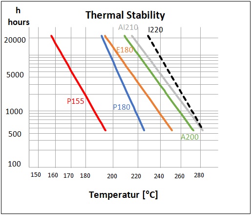
Thermal Stability in Hours [h] vs. Temperature in Degrees Celsius [°C]
Average breakdown voltage at 20°C
|
|
|
Calculation of Breakdown Voltage (Test acc. to IEC 60851-5 4.)
Solderability of different Wire Types
Tinning time [sec] for wire 0.25mm Grade 1 vs. Tin bath temp. [°C]
|
Product-Code
|
AB15
|
FS15
|
FSP18
|
FS18
|
PSP15
|
STP18
|
QTP18
|
RT21
|
|---|---|---|---|---|---|---|---|---|
| Product-Name | Butybond AB15 | Solabond FS15 | Solabond FSP18 | Solabond FS18 | Solabond PSP15 | Thermobond STP18 | Thermobond QTP18 | Thermobond RT21 |
| General Description | ||||||||
| Base coat | mod. Polyurethane | mod. Polyurethane | mod. Polyurethane | Polyesterimide | mod. Polyurethane | mod. Polyurethane | mod. Polyurethane | A200 + Polyamidimide |
| Bond coat | Polyvinylbutyral | Polyamide | Polyamide | Polyamide | Polyamide | Polyamide | Polyamide | aromatic Polyamide |
| IEC (including the following norms) | IEC 60317-35, 60317-2 | IEC 60317-35, 60317-2 | IEC 60317-36 | IEC 60317-35, 60317-2 | IEC 60317-35 | IEC 60317-38 | ||
| NEMA (including the following norms) | MW 131-C | MW 131 | MW 131 | MW 131 | MW 131 | MW 102 | ||
| Diameters available | 0.01 - 0.50 mm | 0.01 - 0.50 mm | 0.01 - 0.50 mm | 0.01 - 0.50 mm | 0.01 - 0.50 mm | 0.01 - 0.50 mm | 0.015 - 0.50 mm | 0.015 - 0.50 mm |
| Properties | Low bonding temperature, wide process window, non-hygroscopic | All bonding methods applicable, good processability, hygroscopic (not suited for humid regions) | All bonding methods applicable, good processability, hygroscopic | Solvent bonding possible, high resoftening temperature, high thermal and mechanical properties of base coat, hygroscopic thus not suitable for Asia | All purpose selfbonding enamel, wide process window, high bonding strength, thermosetting applicable, non-hygroscopic | Good winding ability, thermosetting applicable | higher thermal and mechanical properties, very high resoftening temperature after thermosetting | very high thermal and mechanical properties, very high resoftening temperature |
| Shelf life in months (at 25°C / 60% rel. humidity) |
≤ 6 | ≤ 3 (hygroscopic) | ≤ 5 (hygroscopic) | ≤ 5 (hygroscopic) | ≤ 6 | ≤ 6 | ≤ 6 | ≤ 6 |
| Applications | Stepping motors for quartz watches, instrument coils, voice coils, Sensors, Transponders | Loudspeakers, small motors, sensors, Transponders | Loudspeakers, small motors, sensors, Transponders | Loudspeakers, small motors, sensors, Transponders | Instrument coils, loudspeakers, vibration motors, sensors, receiver and speaker for mobile phones | High power speaker, vibration motors | high power speaker and receiver, micro speaker, high temperature applications | motors, loudspeakers |
| Thermal values of base coat | ||||||||
| Temperature index 20.000 h acc. to IEC 60172 | 158°C | 158°C | 192°C | 195°C | 158°C | 192°C | 192°C | 212°C |
| Thermal stability chart [view] | ||||||||
| Cut through temperature | ||||||||
| 0.05mm: acc. to IEC 60851-6 4 | ≥ 200°C | ≥ 200°C | ≥ 230°C | ≥ 265°C | ≥ 200°C | ≥ 230°C | ≥ 230°C | ≥ 320°C |
| Elektrisola typical value | 225°C | 225°C | 260°C | 315°C | 225°C | 260°C | 260°C | 365°C |
| 0.25mm: acc. to IEC 60851-6 4 | ≥ 200°C | ≥ 200°C | ≥ 230°C | ≥ 265°C | ≥ 200°C | ≥ 230°C | ≥ 230°C | ≥ 320°C |
| Elektrisola typical value | 230°C | 230°C | 265°C | 325°C | 230°C | 265°C | 265°C | 380°C |
| Heat Shock | ||||||||
| 0.05mm: acc. to IEC 60851-6 3 | ≥ 175°C | ≥ 175°C | ≥ 200°C | ≥ 200°C | ≥ 175°C | ≥ 200°C | ≥ 200°C | ≥ 220°C |
| Elektrisola typical value | 190°C | 190°C | 210°C | 260°C | 190°C | 210°C | 210°C | 250°C |
| 0.25mm: acc. to IEC 60851-6 3 | ≥ 175°C | ≥ 175°C | ≥ 200°C | ≥ 200°C | ≥ 175°C | ≥ 200°C | ≥ 200°C | ≥ 220°C |
| Elektrisola typical value | 180°C | 180°C | 200°C | 250°C | 180°C | 200°C | 200°C | 240°C |
| Electrical values | ||||||||
| Low voltage continuity for Grade 1B wires | ||||||||
| 0.05mm: acc. to IEC 60851-5 1 | ≤ 40 | ≤ 40 | ≤ 40 | ≤ 40 | ≤ 40 | ≤ 40 | ≤ 40 | ≤ 40 |
| Elektrisola typical value | 0 | 0 | 0 | 0 | 0 | 0 | 0 | 0 |
| High voltage continuity for Grade 1B wires | ||||||||
| 0.05mm: Elektrisola typical value | 0 | 0 | 0 | 0 | 0 | 0 | 0 | 0 |
| 0.25mm: acc. to IEC 60851-5 2 | ≤ 10 | ≤ 10 | ≤ 10 | ≤ 10 | ≤ 10 | ≤ 10 | ≤ 10 | ≤ 10 |
| 0.25mm: Elektrisola typical value | 0 | 0 | 0 | 0 | 0 | 0 | 0 | 0 |
| Breakdown voltage acc. to IEC 60851-5 4 (at 20 °C, 35% humidity) | ||||||||
| 0.05mm: Elektrisola typical value | 160 V/µm | 160 V/µm | 160 V/µm | 160 V/µm | 160 V/µm | 160 V/µm | 160 V/µm | 160 V/µm |
| 0.25mm: Elektrisola typical value | 120 V/µm | 120 V/µm | 120 V/µm | 120 V/µm | 120 V/µm | 120 V/µm | 120 V/µm | 120 V/µm |
| Calculation method of break voltage [view] | ||||||||
| Pinholes acc. to IEC 60851-5 7 | ||||||||
| with 0.05mm: 0% elongation | good | good | very good | very good | very good | very good | ||
| with 0.25mm: 0% elongation | good | good | very good | very good | very good | very good | ||
| Mechanical values | ||||||||
| Elongation for Grade 1B wire | ||||||||
| 0.05mm: acc. to IEC 60851-3 3.1 | ≥ 14% | ≥ 14% | ≥ 14% | ≥ 14% | ≥ 14% | ≥ 14% | ≥ 14% | ≥ 14% |
| Elektrisola typical value | 23% | 23% | 23% | 23% | 23% | 23% | 23% | 23% |
| 0.25mm: acc. to IEC 60851-3 3.1 | ≥ 25% | ≥ 25% | ≥ 25% | ≥ 25% | ≥ 25% | ≥ 25% | ≥ 25% | ≥ 25% |
| Elektrisola typical value | 40% | 40% | 40% | 40% | 40% | 40% | 40% | 40% |
| Tensile strength for Grade 1B wires | ||||||||
| 0.05mm: Elektrisola typical value | 57 cN | 57 cN | 57 cN | 57 cN | 57 cN | 57 cN | 57 cN | 57 cN |
| 0.25mm: Elektrisola typical value | 1370 cN | 1370 cN | 1370 cN | 1370 cN | 1370 cN | 1370 cN | 1370 cN | 1370 cN |
| Stress strain chart [view] | ||||||||
| Bonding of wire | ||||||||
| Hot air bonding | 0.01 - 0.50 mm | 0.01 - 0.50 mm | 0.015 - 0.50 mm | 0.01 - 0.50 mm | 0.01 - 0.50 mm | 0.01 - 0.50 mm | 0.015 – 0.50 mm | limited |
| Oven bonding | 0.10 - 0.50 mm | 0.10 - 0.50 mm | 0.10 - 0.50 mm | 0.10 - 0.50 mm | 0.10 - 0.50 mm | 0.10 - 0.50 mm | 0.10 – 0.50 mm | 0.10 – 0.50 mm |
| Resistance bonding | 0.10 - 0.50 mm | 0.10 - 0.50 mm | 0.10 - 0.50 mm | 0.10 - 0.50 mm | 0.10 - 0.50 mm | 0.10 - 0.50 mm | 0.10 – 0.50 mm | 0.10 – 0.50 mm |
| Solvent bonding | limited | suitable | suitable | suitable | not suitable | not suitable | not suitable | not suitable |
| Recommended solvent | Ethanol / Methanol | Ethanol / Methanol | Ethanol / Methanol | Ethanol / Methanol | N/A | N/A | N/A | N/A |
| Recommended bonding temperature | 120 - 140°C | 150 - 170°C | 150 - 170°C | 150 - 170°C | 150 - 170°C | 180 - 200°C | 200 – 220°C | 200 – 220°C |
| Resoftening temperature for 0.25mm (IEC 60851-3 7.1.2.4) |
≥ 100°C | ≥ 140°C | ≥ 170°C | ≥ 180°C | ≥ 180°C | ≥ 145°C | ≥ 190°C | ≥ 200°C |
| Bond strength chart | ||||||||
| RoHS laboratory analysis | view | view | view | view | view | |||
| Solderability | ||||||||
| Solderability for Grade 1B wires | ||||||||
| 0.05mm: max. acc. to IEC 60851-4 5 | 2.0s / 390°C | 2.0s / 390°C | 2.0s / 390°C | 3.0s / 470°C | 2.0s / 390°C | 3.0s / 390°C | 3.0s / 390°C | --- |
| Elektrisola typical value | 0.8s / 390°C | 0.4s / 390°C | 0.7s / 390°C | 1.3s / 470°C | 0.4s / 390°C | 0.4s / 420°C | 1.0s / 390°C | --- |
| Elektrisola typical value | 1.5s / 370°C | 0.5s / 370°C | 1.0s / 370°C | 0.7s / 370°C | --- | |||
| 0.25mm: max. acc. to IEC 60851-4 5 | 3.0s / 390°C | 3.0s / 390°C | 3.0s / 390°C | 3.0s / 470°C | 3.0s / 390°C | 3.0s / 390°C | 3.0s / 390°C | --- |
| Elektrisola typical value | 1.4s / 390°C | 0.7s / 390°C | 1.6s / 390°C | 3.0s / 470°C | 0.7s / 390°C | 0.8s / 420°C | 2.0s / 390°C | --- |
| Elektrisola typical value | 2.0s / 370°C | 1.2s / 370°C | 2.8s / 370°C | 1.2s / 370°C | ||||
| Solderability of different wire types chart [view] |
Asia (standard)
Selfbonding Copper Wire acc. to IEC
|
Product-Code
|
BQP15
|
CSP15
|
ES22
|
ESP15
|
KSP15
|
KSP18
|
KS18
|
KS22
|
|---|---|---|---|---|---|---|---|---|
| Product-Name | Polyesterbond BQP15 | Solabond CSP15 | Solabond ES22 | Solabond ESP15 | Solabond KSP15 | Solabond KSP18 | Solabond KS18 | Solabond KS22 |
| General Description | ||||||||
| Base coat | mod. Polyurethane | mod. Polyurethane | Polyamideimide | mod. Polyurethane | mod. Polyurethane | mod. Polyurethane | Polyesterimide | Polyamideimide |
| Bond coat | mod. Polyester | Polyamide | Polyamide | Polyamide | Polyamide | Polyamide | Polyamide | Polyamide |
| IEC (including the following standards) | IEC 60317-35, 60317-2 | IEC 60317-35, 60317-2 | --- | IEC 60317-35, 60317-2 | IEC 60317-35, 60317-2 | IEC 60317-35 | IEC 60317-36 | --- |
| NEMA (including the following standards) | MW 131 | MW 131 | --- | MW 131 | MW 131 | --- | --- | --- |
| Diameters available | 0.015 - 0.50 mm | 0.015 - 0.50 mm | 0.050 - 0.70 mm | 0.015 - 0.50 mm | 0.015 - 0.50 mm | 0.015 - 0.50 mm | 0.015 - 0.50 mm | 0.050 - 0.60 mm |
| Properties | Easy bonding, wide process window | Excellent solvent bonding, heat bonding possible | Suitable for hot air bonding, very high thermal properties of base coat | Suitable for hot air bonding, very good winding properties | Suitable for hot air bonding, excellent solderability | Suitable for hot air bonding, high thermal properties of base coat | Suitable for hot air bonding, higher thermal properties of base coat | Suitable for hot air bonding, very high thermal properties of base coat |
| Shelf life in months (at 25°C / 60% rel. humidity) |
≤6 | ≤6 | ≤6 | ≤6 | ≤6 | ≤6 | ≤6 | ≤6 |
| Applications | For sensors, instrument coils, RFID, transponders, card application | For voice coils, small motor, vibration motors, transponders | For molding inductor, small motor | For sensors, instrument coils, voice coils, vibration motors | For small motor, instrument coils, loudspeaker, sensors | For small motor, instrument coils, loudspeaker, sensors, transponders | For small motor, loudspeaker | For small motor, inductor |
| Thermal values of base coat | ||||||||
| Temperature index 20.000 h acc. IEC 60172 | 164°C | 164°C | 230°C | 164°C | 164°C | 192°C | 195°C | 230°C |
| Cut through temperature min. °C acc. to IEC 60851-6 4. | ≥ 200°C | ≥ 200°C | ≥ 350°C | ≥ 200°C | ≥ 200°C | ≥ 230°C | ≥ 265°C | ≥ 350°C |
| ELEKTRISOLA-typical values for 0.05 mm/0.25 mm, Grade 1B | 225 / 230°C | 225 / 230°C | 390 / 410°C | 225 / 230°C | 225 / 230°C | 260 / 265°C | 315 / 325°C | 390 / 410°C |
| Heat shock min. °C acc. to IEC 60851-6 3. | ≥ 175°C | ≥ 175°C | ≥ 240°C | ≥ 175°C | ≥ 175°C | ≥ 200°C | ≥ 200°C | ≥ 240°C |
| ELEKTRISOLA-typical values for 0.05 mm/0.25 mm, Grade 1B | 190 / 180°C | 190 / 180°C | 250 / 240°C | 190 / 180°C | 190 / 180°C | 210 / 200°C | 260 / 250°C | 250 / 240°C |
| Electrical values | ||||||||
| Low voltage continuity max. acc. to IEC 60851-5 5.2 for 0.05 mm | ≤ 40 | ≤ 40 | ≤ 40 | ≤ 40 | ≤ 40 | ≤ 40 | ≤ 40 | ≤ 40 |
| ELEKTRISOLA-typical values for 0.05 mm, Grade 1B | 0 | 0 | 0 | 0 | 0 | 0 | 0 | 0 |
| High voltage continuity max. acc. to IEC 60851-5 5.3 for 0.25 mm | ≤ 10 | ≤ 10 | ≤ 10 | ≤ 10 | ≤ 10 | ≤ 10 | ≤ 10 | ≤ 10 |
| ELEKTRISOLA-typical values for 0.25 mm, Grade 1B | 0 | 0 | 0 | 0 | 0 | 0 | 0 | 0 |
| Breakdown voltage acc. IEC 60851-5 4., (at 20°C, 35% humidity) | ||||||||
| ELEKTRISOLA-typical values for 0.05 mm/0.25 mm, Grade 1B | 160 / 120 V/μm | 160 / 120 V/μm | 160 / 120 V/µm | 160 / 120 V/μm | 160 / 120 V/μm | 160 / 120 V/μm | 160 / 120 V/μm | 160 / 120 V/μm |
| Mechanical values | ||||||||
| Elongation min. acc. to IEC 60851-3 3.1 for 0.05 mm/0.25 mm, Grade 1B | ≥ 14% / ≥ 25% | ≥ 14% / ≥ 25% | ≥ 14% / ≥ 25% | ≥ 14% / ≥ 25% | ≥ 14% / ≥ 25% | ≥ 14% / ≥ 25% | ≥ 14% / ≥ 25% | ≥ 14% / ≥ 25% |
| ELEKTRISOLA-typical values for 0.05 mm/0.25 mm, Grade 1B | 23% / 40% | 23% / 40% | 23% / 40% | 23% / 40% | 23% / 40% | 23% / 40% | 23% / 40% | 23% / 40% |
| Tensile strength | ||||||||
| ELEKTRISOLA-typical values for 0.05 mm/0.25 mm, Grade 1B | 57 / 1370 cN | 57 / 1370 cN | 57 / 1370 cN | 57 / 1370 cN | 57 / 1370 cN | 57 / 1370 cN | 57 / 1370 cN | 57 / 1370 cN |
| Bonding of wire | ||||||||
| Hot air bonding | Suitable | Suitable | Suitable | Suitable | Suitable | Suitable | Suitable | Suitable |
| Oven bonding | Suitable | Suitable | Suitable | Suitable | Suitable | Suitable | Suitable | Suitable |
| Resistance bonding | Suitable | Suitable | Suitable | Suitable | Suitable | Suitable | Suitable | Suitable |
| Solvent bonding | Not suitable | Suitable | Not suitable | Not suitable | Not suitable | Not suitable | Not suitable | Not suitable |
| Recommended solvent | -- | Ethanol / Isopropanol | --- | --- | --- | --- | --- | --- |
| Recommended bonding temperature | 120 - 140°C | 170 - 200°C | 160 - 190°C | 160 - 190°C | 150 - 170°C | 150 - 170°C | 150 - 170°C | 150 - 170°C |
| Resoftening temperature | ≥ 90°C | ≥ 140°C | ≥ 130°C | ≥ 130°C | ≥ 105°C | ≥ 105°C | ≥ 105°C | ≥ 105°C |
| Solderability | ||||||||
| Acc. to IEC 60851-4 5. max . seconds at °C for 0.05 mm/0.25 mm, Grade 1B | 2.0s/390°C / 3.0s/390°C | 2.0s/390°C / 3.0s/390°C | Not Solderable | 2.0s/390°C / 3.0s/390°C | 2.0s/390°C / 3.0s/390°C | 3.0s/390°C / 3.0s/390°C | 3.0s/470°C / 3.0s/470°C | Not Solderable |
| ELEKTRISOLA-typical values IEC 60851-4 5. | ||||||||
| for 0.05 mm, Grade 1B, | 0.5s/370°C / 0.4s/390°C | 1.0s/370°C / 0.6s/390°C | --- | 1.0s/370°C / 0.6s/390°C | 0.5s/370°C / 0.4s/390°C | 1.0s/370°C / 0.7s/390°C | 1.9s/470°C | --- |
| seconds at °C | ||||||||
| for 0.25 mm, Grade 1B, | 1.2s/370°C / 0.7s/390°C | 1.6s/370°C / 0.8s/390°C | --- | 1.6s/370°C / 0.8s/390°C | 1.2s/370°C / 0.7s/390°C | 2.8s/370°C / 1.6s/390°C | 3.4s/470°C | --- |
| seconds at °C |
Asia (high performance)
Selfbonding Copper Wire acc. to IEC
|
Product-Code
|
PSP15
|
PSP18
|
STP18
|
KTP18
|
KT22
|
LTP18
|
ETP18
|
ET22
|
|---|---|---|---|---|---|---|---|---|
| Product-Name | Solabond PSP15 | Solabond PSP18 | Thermobond STP18 | Thermobond KTP18 | Thermobond KT22 | Thermobond LTP18 | Thermobond ETP18 | Thermobond ET22 |
| General Description | ||||||||
| Base coat | mod.Polyurethane | mod.Polyurethane | mod.Polyurethane | mod.Polyurethane | mod.Polyamidimide | mod.Polyurethane | mod.Polyurethane | mod.Polyamidimide |
| Bond coat | Polyamide | Polyamide | Polyamide | Polyamide | Polyamide | Polyamide | Polyamide | Polyamide |
| IEC (including the following standards) | IEC 60317-35, 60317-2 | IEC 60317-35 | IEC 60317-35 | IEC 60317-35 | --- | IEC 60317-35 | IEC 60317-35 | --- |
| NEMA (including the following standards) | MW 131 | --- | MW 131 | --- | --- | --- | --- | --- |
| Diameters available | 0.010 - 0.50 mm | 0.010 - 0.50 mm | 0.015 - 0.50 mm | 0.015 - 0.50 mm | 0.015 - 0.50 mm | 0.015 - 0.50 mm | 0.015 - 0.50 mm | 0.015 - 0.50 mm |
| Properties | high resoftening temperature after thermosetting, very good properties for hot-air bonding, very good winding properties, non-hyproscopic | Thermosetting possible, high bonding strength, non-hygroscopic | Higher thermal and mechanical properties, very high resoftening temperature after thermosetting, non-hygroscopic | High resoftening temperature, suitable for High Current Test (HCT), high bonding strength, non-hygroscopic | Very High resoftening temperature, suitable for High Current Test (HCT), high bonding strength, non-hygroscopic | High resoftening temperature, suitable for High Current Test (HCT), high bonding strength, non-hygroscopic | Excellent winding performance, high resoftening temperature, high bonding strength at the coil ends, suitable for High Current Test (HCT), non-hygroscopic | Excellent winding performance, high resoftening temperature, high bonding strength at the coil ends, suitable for High Current Test (HCT), non-hygroscopic |
| Shelf life in months (at 25°C / 60% rel. humidity) |
≤6 | ≤6 | ≤6 | ≤6 | ≤6 | ≤6 | ≤6 | ≤6 |
| Applications | Instrument coils, loudspeakers, small motors, sensors, receiver and speaker for mobile phones | Instrument coils, loudspeakers, motors, sensors | High power speaker and receiver, micro speaker, high temperature applications | High power speaker / receiver, Micro speaker | High power speaker / receiver, Micro speaker | Loudspeakers, Stepping motors, Voice coils, Sensors, Transponders | High power speaker / receiver, Micro speaker | High power speaker / receiver, Micro speaker |
| Thermal values of base coat | ||||||||
| Temperature index 20.000 h acc. IEC 60172 | 158°C | 192°C | 192°C | 192°C | 230°C | 192°C | 192°C | 230°C |
| Cut through temperature min. °C acc. to IEC 60851-6 4. | ≥ 200°C | ≥ 230°C | ≥ 230°C | ≥ 230°C | ≥ 350°C | ≥ 230°C | ≥ 230°C | ≥ 350°C |
| ELEKTRISOLA-typical values for 0.05 mm/0.25 mm, Grade 1B | 225 / 230°C | 260 / 265°C | 260 / 265°C | 260 / 265°C | 390 / 410°C | 260 / 265°C | 260 / 265°C | 390 / 410°C |
| Heat shock min. °C acc. to IEC 60851-6 3. | ≥ 175°C | ≥ 200°C | ≥ 200°C | ≥ 200°C | ≥ 220°C | ≥ 200°C | ≥ 200°C | ≥ 200°C |
| ELEKTRISOLA-typical values for 0.05 mm/0.25 mm, Grade 1B | 190 / 180°C | 210 / 200°C | 210 / 200°C | 210 / 200°C | 250 / 240°C | 210 / 200°C | 210 / 200°C | 250 / 240°C |
| Electrical values | ||||||||
| Low voltage continuity max. acc. to IEC 60851-5 5.2 for 0.05 mm Grade 1 B | ≤ 40 | ≤ 40 | ≤ 40 | ≤ 40 | ≤ 40 | ≤ 40 | ≤ 40 | ≤ 40 |
| ELEKTRISOLA-typical values for 0.05 mm, Grade 1B | 0 | 0 | 0 | 0 | 0 | 0 | 0 | 0 |
| High voltage continuity max. acc. to IEC 60851-5 5.3 for 0.25 mm Grade 1B | ≤ 10 | ≤ 10 | ≤ 10 | ≤ 10 | ≤ 10 | ≤ 10 | ≤ 10 | ≤ 10 |
| ELEKTRISOLA-typical values for 0.25 mm, Grade 1B | 0 | 0 | 0 | 0 | 0 | 0 | 0 | 0 |
| Breakdown voltage acc. IEC 60851-5 4., (at 20°C, 35% humidity) | ||||||||
| ELEKTRISOLA-typical values test for 0.05 mm/0.25 mm, Grade 1B | 160 / 120 V/μm | 160 / 120 V/μm | 160 / 120 V/μm | 160 / 120 V/μm | 160 / 120 V/μm | 160 / 120 V/μm | 160 / 120 V/μm | 160 / 120 V/μm |
| Mechanical values | ||||||||
| Elongation min. acc. to 60851-3 3.1 for 0.05 mm/0.25 mm, Grade 1B | ≥ 14% / ≥ 25% | ≥ 14% / ≥ 25% | ≥ 14% / ≥ 25% | ≥ 14% / ≥ 25% | ≥ 14% / ≥ 25% | ≥ 14% / ≥ 25% | ≥ 14% / ≥ 25% | ≥ 14% / ≥ 25% |
| ELEKTRISOLA-typical values for 0.05 mm/0.25 mm, Grade 1B | 23% / 40% | 23% / 40% | 23% / 40% | 23% / 40% | 23% / 40% | 23% / 40% | 23% / 40% | 23% / 40% |
| Tensile strength | ||||||||
| ELEKTRISOLA-typical values for 0.05 mm/0.25 mm, Grade 1B | 57 / 1370 cN | 57 / 1370 cN | 57 / 1370 cN | 57 / 1370 cN | 57 / 1370 cN | 57 / 1370 cN | 57 / 1370 cN | 57 / 1370 cN |
| Bonding of wire | ||||||||
| Hot air bonding | 0.010-0.50mm | 0.010-0.50mm | 0.015-0.50mm | 0.015-0.50mm | 0.015-0.50mm | Limited | 0.015-0.50mm | 0.015-0.50mm |
| Oven bonding | 0.100-0.50mm | 0.100-0.50mm | 0.100-0.50mm | 0.100-0.50mm | 0.100-0.50mm | Limited | 0.100-0.50mm | 0.100-0.50mm |
| Resistance bonding | 0.100-0.50mm. | 0.100-0.50mm | 0.100-0.50mm | 0.100-0.50mm | 0.100-0.50mm | Limited | 0.100-0.50mm | 0.100-0.50mm |
| Solvent bonding | Not suitable | Not suitable | Not suitable | Not suitable | Not suitable | 0.015-0.50mm | Not suitable | Not suitable |
| Recommended solvent | --- | --- | --- | --- | --- | Ethanol/Methanol | --- | --- |
| Recommended bonding temperature | 150 - 170°C | 150 - 170°C | 180 - 200°C | 220°C | 220°C | 220°C | 220°C | 220°C |
| Resoftening temperature (after postbacking) | ≥ 125°C (180°C) | ≥ 125°C (180°C) | ≥ 145°C (190°C) | ≥ 230°C | ≥ 230°C | ≥ 210°C | ≥ 260°C | ≥ 260°C |
| Solderability | ||||||||
| acc. to IEC 60851-4 5. max . seconds at °C for 0.05 mm/0.25 mm, Grade 1B | 2.0s/390°C / 3.0s/390°C | 3.0s/390°C / 3.0s/390°C | 3.0s/390°C / 3.0s/390°C | 3.0s/390°C / 3.0s/390°C | Not solderable | 3.0s/390°C / 3.0s/390°C | 3.0s/390°C / 3.0s/390°C | Not solderable |
| ELEKTRISOLA-typical values IEC 60851-4 5. | ||||||||
| for 0.05 mm, Grade 1B, | 0.7s/370°C / 0.4s/390°C | 1.2s/390°C | 0.4s/420°C | 0.5s/470°C | --- | n.a/420°C | 0.6s/470°C | --- |
| seconds at °C | ||||||||
| for 0.25 mm, Grade 1B, | 1.2s/370°C / 0.7s/390°C | 1.5s/390°C | 0.8s/420°C | --- | --- | n.a/420°C | --- | --- |
| seconds at °C |
America
Selfbonding Copper Wire acc. to NEMA
| Product-Code
|
ABN15
|
FS15
|
FSP18
|
FS18
|
AE21
|
AQ21
|
UT18
|
RT21
|
|---|---|---|---|---|---|---|---|---|
| General Description | ||||||||
| Base Coat / Base Coat Type | mod. Polyurethane+Polyamide | mod. Polyurethane | mod. Polyurethane | Polyesterimide | A200 + Polyamidimide | A200 + Polyamidimide | Polyesterimide | A200 + Polyamidimide |
| Bond Coat / Bond Coat Type | Polyvinylbutyral | Polyamide | Polyamide | Polyamide | Epoxy | Polyester | Polyamide | Aromatic Polyamide |
| NEMA (including the following norms) | MW136 | MW131 | MW137 | MW102 | MW102 | |||
| IEC (including the following norms) | IEC 60317-35, 60317-2 | IEC 60317-35, 60317-2 | IEC 60317-35 | IEC 60317-36 | IEC 60317-38 | IEC 60317-38 | IEC 60317-36 | IEC 60317-38 |
| Diameter Available | ||||||||
| AWG | 24-58 AWG | 24-58 AWG | 24-58 AWG | 24-54 AWG | 24-58 AWG | 24-54 AWG | 24-54 AWG | 24-58 AWG |
| mm | 0.01 - 0.50 mm | 0.01 - 0.50 mm | 0.01 - 0.50 mm | 0.015 - 0.50 mm | 0.01 - 0.50 mm | 0.015 - 0.50 mm | 0.015 - 0.50 mm | 0.01 - 0.50 mm |
| Properties | Low Bonding Temperature | Solvent Bonding Possible | Solvent bonding possible, higher thermal properties. | Solvent bonding possible, higher thermal properties. | Low bonding temperature & Solvent bonding possible. | High thermal and mechanical properties and high resoftening temperature. | High thermal and mechanical properties, high resoftening temperature. | Very high thermal and mechanical properties, very high resoftening temperature (non hygroscopic) |
| Shelf life in months (at 25°C / 60% rel. humidity) |
≤ 6 | ≤ 3 (hygroscopic) | ≤ 5 (hygroscopic) | ≤ 5 (hygroscopic) | ≤ 6 | ≤ 6 | ≤ 6 (Hygroscopic) | ≤ 6 |
| Applications | Stepper motors for watches, instrument coils, voice coils, sensors, transponders | Instrument coils, loudspeakers, small motors, sensors | Instrument coils, loudspeakers, small motors, sensors, transponders | High power speaker and receiver, micro speaker, high temperature applications | Instrument coils, loudspeakers, small motors, sensors, receiver and speaker for mobile phones | High power speaker and receiver, micro speaker, high temperature applications | High power speaker and receiver, micro speaker, high temperature applications | Motors, loudspeakers |
| Thermal Values of Base Coat | ||||||||
| Temperature index 20.000 h acc. To IEC 60172 | 158°C | 158°C | 192°C | 195°C | 212°C | 212°C | 195°C | 212°C |
| Cut-through Temperature | ||||||||
| Acc. to NEMA MW1000 3.5 for 44/30AWG: | ≥ 200°C / ≥ 200°C | ≥ 200°C / ≥ 200°C | ≥ 230°C / ≥ 230°C | ≥ 225°C | ≥ 320°C | ≥ 320°C | ≥ 265°C | ≥ 320°C |
| Elektrisola typical value for 44/30AWG: | 225°C / 230°C | 225°C / 230°C | 260°C / 265°C | 260°C / 265°C | 365°C / 380°C | 365°C / 380°C | 260°C / 265°C | 365°C / 380°C |
| Heat Shock | ||||||||
| Acc. To NEMA MW1000 3.5 for 44/30AWG: | ≥ 175°C / ≥ 175°C | ≥ 175°C / ≥ 175°C | ≥ 200°C / ≥ 200°C | ≥ 200°C | ≥ 220°C | ≥ 220°C | ≥ 200°C | ≥ 220°C |
| Elektrisola typical value for 44/30AWG: | 190°C / 180°C | 190°C / 180°C | 210°C / 200°C | 310°C / 320°C | 250°C / 240°C | 250°C / 240°C | 310°C / 320°C | 250°C / 240°C |
| Mechanical Values | ||||||||
| Elongation for Type 1 | ||||||||
| Acc. to NEMA MW1000 3.4 for 44/30AWG: | ≥ 10% / ≥ 22% | ≥ 10% / ≥ 22% | ≥ 10% / ≥ 22% | ≥ 14% / ≥ 25% | ≥ 14% / ≥ 25% | ≥ 14% / ≥ 25% | ≥ 14% / ≥ 25% | ≥ 14% / ≥ 25% |
| Elektrisola typical value for 44/30AWG: | 23% / 40% | 23% / 40% | 23% / 40% | 23% / 40% | 23% / 40% | 23% / 40% | 23% / 40% | 23% / 40% |
| Bonding of Wire | ||||||||
| Hot Air Bonding | 24-58 AWG | 24-58 AWG | 24-58 AWG | 24-58 AWG | 24-58 AWG | 24-58 AWG | 24-58 AWG | 24-58 AWG |
| Oven Bonding | 38-24 AWG | 38-24 AWG | 38-24 AWG | 38-24 AWG | 38-24 AWG | 38-24 AWG | 38-24 AWG | 38-24 AWG |
| Resistance Bonding | 38-24 AWG | 38-24 AWG | 38-24 AWG | 38-24 AWG | 38-24 AWG | 38-24 AWG | 38-24 AWG | 38-24 AWG |
| Solvent Bonding | Limited | Suitable | Suitable | Suitable | Suitable | Suitable | N/A | N/A |
| Recommended Solvent | Ethanol / Methanol | Ethanol / Methanol | Ethanol / Methanol | Ethanol / Methanol | Acetone/MEK | Acetone/MEK | ||
| Recommended Bonding Temperature | 120°C - 140°C | 150°C - 170°C | 150°C - 170°C | 180°C - 220°C | 120°C - 140°C | 160°C - 190°C | 180°C - 220°C | 200°C - 220°C |
| Resoftening Temperature for 30AWG | ≥ 100°C | ≥ 140°C | ≥ 170°C | ≥ 180°C | ≥ 100°C | ≥ 180°C | ≥ 180°C | ≥ 200°C |
| Solderability | ||||||||
| Solderability for Type 1 | ||||||||
| Acc. to NEMA MW1000 3.11 for 44/30AWG: | 2.0s/390°C / 3.0s/390°C | 2.0s/390°C / 3.0s/390°C | 2.0s/390°C / 3.0s/390°C | 2.0s/470°C / 3.0s/470°C | - | - | - | |
| Elektrisola typical value for 44 AWG: | 0.8s/390°C / 1.3s/370°C | 0.4s/390°C / 0.5s/370°C | 0.7s/390°C / 1.0s/370°C | 1.6s/470C | - | - | - | |
| Elektrisola typical value for 30 AWG: | 1.4s/390°C / 2.8s/370°C | 0.7s/390°C / 1.2s/370°C | 2.0s/390°C / 2.8s/370°C | 3.0s/470C | - | - | 5.5s/470C | - |
Elektrisola typical values are the result of various tests and represent average values.
We believe that all information in this catalogue is reliable and accurate, but the accuracy or completeness thereof is not guaranted.
EW Technical Data
Technical Data by Size
General
Technical values of enamelled wires often depend on the diameter of the wire.
Most important are the tolerances for resistance and outer diameter. These and other values are important as engineering support.
Different standards specify these values differently. Therefore the 3 major world standards are shown:
- IEC 60317 for Europe and Asia
- JIS C3202 for Asia
- NEMA MW 1000C (inch) and NEMA MW 1000C metric (mm) for America
Printversions can be found below the individual tabs.
Europe / Asia IEC 60317
Technical Data for Enamelled Copper Wire by Size acc. to IEC 60317
| Enamelled Copper Wire (overall diameter) |
Breakdown Voltage acc to IEC ** |
Length of 1 kg of enamelled wire |
Filling Factor number of enamelled wires/cm² | |||||||||||||||||||
|---|---|---|---|---|---|---|---|---|---|---|---|---|---|---|---|---|---|---|---|---|---|---|
| Nominal Diameter |
Conductor (Bare Wire) |
Grade 1 | Grade 2 | Grade 3 | Resistance at 20 °C | Elongation acc to IEC |
Grade 1 | Grade 2 | Grade 3 | Grade 1 | Grade 2 | Grade 3 | Grade 1 | Grade 2 | Grade 3 | Winding Tension | ||||||
[mm] |
tolerance [mm] |
section [mm²] |
min [mm] |
max [mm] |
min [mm] |
max [mm] |
min [mm] |
max [mm] |
nom [Ohm/m] |
min [Ohm/m] |
max [Ohm/m] |
min [%] |
min [V] |
min [V] |
min [V] |
approx. [km] |
approx. [km] |
approx. [km] |
[n] |
[n] |
[n] |
max [cN] |
| 0.010 | * | 0.000078540 | 0.012 | 0.013 | 0.014 | 0.016 | 0.017 | 0.019 | 217.65 | 195.88 | 239.41 | 3 | 70 | 125 | 170 | 1315.6 | 1202.0 | 1069.1 | 739090 | 513257 | 356428 | 1.4 |
| 0.012 | * | 0.00011310 | 0.014 | 0.016 | 0.017 | 0.018 | 0.019 | 0.021 | 151.14 | 136.03 | 166.26 | 3 | 80 | 150 | 190 | 913.6 | 847.9 | 782.9 | 513257 | 377087 | 288707 | 2.0 |
| 0.014 | * | 0.00015394 | 0.016 | 0.018 | 0.019 | 0.020 | 0.021 | 0.023 | 111.04 | 99.94 | 122.15 | 4 | 90 | 175 | 230 | 679.4 | 638.1 | 596.8 | 399595 | 303702 | 238601 | 2.5 |
| 0.016 | * | 0.00020106 | 0.018 | 0.020 | 0.021 | 0.022 | 0.023 | 0.025 | 85.02 | 76.52 | 93.52 | 5 | 100 | 200 | 290 | 524.9 | 497.3 | 469.5 | 319897 | 249828 | 200491 | 3.2 |
| 0.018 | * | 0.00025447 | 0.020 | 0.022 | 0.023 | 0.024 | 0.025 | 0.026 | 67.18 | 60.46 | 73.89 | 5 | 110 | 225 | 350 | 417.6 | 398.3 | 382.7 | 261866 | 209113 | 177598 | 3.9 |
| 0.019 | * | 0.00028353 | 0.021 | 0.023 | 0.024 | 0.026 | 0.027 | 0.028 | 60.29 | 54.26 | 66.32 | 6 | 115 | 240 | 380 | 375.9 | 356.2 | 339.6 | 238601 | 184773 | 152705 | 4.3 |
| 0.020 | * | 0.00031416 | 0.022 | 0.024 | 0.025 | 0.027 | 0.028 | 0.030 | 54.41 | 48.97 | 59.85 | 6 | 120 | 250 | 410 | 340.1 | 323.2 | 306.2 | 218304 | 170833 | 137316 | 4.4 |
| 0.021 | * | 0.00034636 | 0.023 | 0.026 | 0.027 | 0.028 | 0.029 | 0.031 | 49.35 | 44.42 | 54.29 | 6 | 125 | 265 | 440 | 306.8 | 292.2 | 279.9 | 192391 | 152705 | 128314 | 5.1 |
| 0.022 | * | 0.00038013 | 0.024 | 0.027 | 0.028 | 0.030 | 0.031 | 0.033 | 44.97 | 40.47 | 49.47 | 6 | 130 | 275 | 470 | 280.2 | 265.4 | 252.6 | 177598 | 137316 | 112776 | 5.5 |
| 0.023 | * | 0.00041548 | 0.025 | 0.028 | 0.029 | 0.031 | 0.032 | 0.034 | 41.14 | 37.03 | 45.26 | 7 | 145 | 290 | 470 | 257.0 | 244.0 | 232.8 | 164447 | 128314 | 106045 | 6.0 |
| 0.024 | * | 0.00045239 | 0.026 | 0.029 | 0.030 | 0.032 | 0.033 | 0.035 | 37.79 | 34.01 | 41.56 | 7 | 145 | 290 | 470 | 236.5 | 225.1 | 215.3 | 152705 | 120169 | 99899 | 6.5 |
| 0.025 | * | 0.00049087 | 0.028 | 0.031 | 0.032 | 0.034 | 0.035 | 0.037 | 34.82 | 31.34 | 38.31 | 7 | 150 | 300 | 470 | 215.5 | 205.4 | 196.7 | 132701 | 106045 | 89107 | 7.0 |
| 0.027 | * | 0.00057256 | 0.030 | 0.033 | 0.034 | 0.036 | 0.037 | 0.040 | 29.86 | 26.87 | 32.84 | 7 | 165 | 315 | 510 | 185.6 | 177.6 | 169.5 | 116385 | 94272 | 77910 | 8.0 |
| 0.028 | * | 0.00061575 | 0.031 | 0.034 | 0.035 | 0.038 | 0.039 | 0.042 | 27.76 | 24.99 | 30.54 | 7 | 170 | 325 | 530 | 172.9 | 164.7 | 156.4 | 109333 | 86683 | 70406 | 8.5 |
| 0.030 | * | 0.00070686 | 0.033 | 0.037 | 0.038 | 0.041 | 0.042 | 0.044 | 24.18 | 21.76 | 26.60 | 8 | 180 | 350 | 560 | 150.3 | 142.8 | 136.9 | 94272 | 74016 | 62457 | 9.6 |
| 0.032 | * | 0.00080425 | 0.035 | 0.039 | 0.040 | 0.043 | 0.044 | 0.047 | 21.25 | 19.13 | 23.38 | 8 | 190 | 375 | 590 | 132.6 | 126.4 | 120.8 | 84356 | 67053 | 55782 | 10.8 |
| 0.034 | * | 0.00090792 | 0.037 | 0.041 | 0.042 | 0.046 | 0.047 | 0.050 | 18.83 | 17.13 | 20.52 | 8 | 210 | 400 | 620 | 117.8 | 112.1 | 106.9 | 75926 | 59650 | 49095 | 12.0 |
| 0.036 | * | 0.0010179 | 0.040 | 0.044 | 0.045 | 0.049 | 0.050 | 0.053 | 16.79 | 15.28 | 18.31 | 8 | 225 | 425 | 650 | 104.4 | 99.57 | 95.18 | 65466 | 52278 | 43541 | 13.2 |
| 0.038 | * | 0.0011341 | 0.042 | 0.046 | 0.047 | 0.051 | 0.052 | 0.055 | 15.07 | 13.72 | 16.43 | 10 | 240 | 450 | 680 | 93.97 | 89.87 | 86.14 | 59650 | 48098 | 40347 | 14.5 |
| 0.040 | * | 0.0012566 | 0.044 | 0.049 | 0.050 | 0.054 | 0.055 | 0.058 | 13.60 | 12.38 | 14.83 | 10 | 250 | 475 | 710 | 84.68 | 80.81 | 77.61 | 53409 | 42708 | 36176 | 15.9 |
| 0.043 | * | 0.0014522 | 0.047 | 0.052 | 0.053 | 0.058 | 0.059 | 0.063 | 11.77 | 10.71 | 12.83 | 12 | 265 | 520 | 710 | 73.55 | 70.15 | 67.01 | 47131 | 37491 | 31035 | 18.0 |
| 0.045 | * | 0.0015904 | 0.050 | 0.055 | 0.056 | 0.061 | 0.062 | 0.066 | 10.75 | 9.781 | 11.72 | 12 | 275 | 550 | 710 | 66.82 | 63.85 | 61.10 | 41899 | 33745 | 28194 | 19.4 |
| 0.048 | * | 0.0018096 | 0.053 | 0.059 | 0.060 | 0.064 | 0.065 | 0.069 | 9.447 | 8.596 | 10.30 | 14 | 290 | 580 | 780 | 58.73 | 56.28 | 54.22 | 36825 | 30042 | 25726 | 21.7 |
| 0.050 | * | 0.0019635 | 0.055 | 0.060 | 0.061 | 0.066 | 0.067 | 0.072 | 8.706 | 7.922 | 9.489 | 14 | 300 | 600 | 830 | 54.42 | 52.26 | 50.08 | 34929 | 28640 | 23908 | 23.2 |
| 0.053 | * | 0.0022062 | 0.058 | 0.064 | 0.065 | 0.070 | 0.071 | 0.076 | 7.748 | 7.051 | 8.446 | 15 | 315 | 625 | 860 | 48.42 | 46.45 | 44.62 | 31035 | 25346 | 21377 | 25.6 |
| 0.056 | * | 0.0024630 | 0.062 | 0.067 | 0.068 | 0.074 | 0.075 | 0.079 | 6.940 | 6.316 | 7.565 | 15 | 325 | 650 | 890 | 43.36 | 41.69 | 40.14 | 27759 | 22909 | 19478 | 28.2 |
| 0.060 | * | 0.0028274 | 0.066 | 0.072 | 0.073 | 0.079 | 0.080 | 0.085 | 6.046 | 5.502 | 6.590 | 16 | 355 | 680 | 960 | 37.79 | 36.33 | 34.97 | 24256 | 19994 | 16967 | 31.7 |
| 0.063 | * | 0.0031172 | 0.069 | 0.076 | 0.077 | 0.083 | 0.084 | 0.088 | 5.484 | 4.990 | 5.977 | 16 | 375 | 700 | 1020 | 34.27 | 32.92 | 31.83 | 21971 | 18044 | 15614 | 34.4 |
| 0.067 | ±0.003 | 0.0035257 | 0.074 | 0.080 | 0.081 | 0.088 | 0.089 | 0.091 | 4.848 | 4.412 | 5.285 | 17 | 400 | 700 | 1060 | 30.31 | 29.19 | 28.36 | 19478 | 16173 | 14257 | 38 |
| 0.070 | ±0.003 | 0.0038485 | 0.077 | 0.083 | 0.084 | 0.090 | 0.091 | 0.096 | 4.442 | 4.042 | 4.842 | 17 | 425 | 700 | 1100 | 27.83 | 26.91 | 26.06 | 18044 | 15257 | 13210 | 41 |
| 0.071 | ±0.003 | 0.0039592 | 0.078 | 0.084 | 0.085 | 0.091 | 0.092 | 0.096 | 4.318 | 3.929 | 4.706 | 17 | 425 | 700 | 1100 | 27.07 | 26.19 | 25.43 | 17601 | 14913 | 13070 | 42 |
| 0.075 | ±0.003 | 0.0044179 | 0.082 | 0.089 | 0.090 | 0.095 | 0.096 | 0.102 | 3.869 | 3.547 | 4.235 | 17 | 425 | 765 | 1140 | 24.26 | 23.52 | 22.82 | 15797 | 13497 | 11783 | 46 |
| 0.080 | ±0.003 | 0.0050265 | 0.087 | 0.094 | 0.095 | 0.101 | 0.102 | 0.108 | 3.401 | 3.133 | 3.703 | 17 | 425 | 850 | 1200 | 21.39 | 20.73 | 20.11 | 14100 | 12024 | 10475 | 52 |
| 0.085 | ±0.003 | 0.0056745 | 0.093 | 0.100 | 0.101 | 0.107 | 0.108 | 0.114 | 3.012 | 2.787 | 3.265 | 18 | 465 | 875 | 1250 | 18.92 | 18.37 | 17.86 | 12401 | 10677 | 9373 | 57 |
| 0.090 | ±0.003 | 0.0063617 | 0.098 | 0.105 | 0.106 | 0.113 | 0.114 | 0.120 | 2.687 | 2.495 | 2.900 | 18 | 500 | 900 | 1300 | 16.92 | 16.43 | 15.96 | 11209 | 9631 | 8436 | 63 |
| 0.095 | ±0.003 | 0.0070882 | 0.103 | 0.111 | 0.112 | 0.119 | 0.120 | 0.126 | 2.412 | 2.247 | 2.594 | 19 | 500 | 925 | 1350 | 15.19 | 14.75 | 14.35 | 10087 | 8657 | 7633 | 69 |
| 0.100 | ±0.003 | 0.0078540 | 0.108 | 0.117 | 0.118 | 0.125 | 0.126 | 0.132 | 2.176 | 2.034 | 2.333 | 19 | 500 | 950 | 1400 | 13.72 | 13.31 | 12.97 | 9125 | 7823 | 6940 | 75 |
| 0.106 | ±0.003 | 0.0088247 | 0.115 | 0.123 | 0.124 | 0.132 | 0.133 | 0.140 | 1.937 | 1.816 | 2.069 | 20 | 1200 | 2650 | 3800 | 12.22 | 11.88 | 11.56 | 8155 | 7049 | 6198 | 83 |
| 0.110 | ±0.003 | 0.0095033 | 0.119 | 0.128 | 0.129 | 0.137 | 0.138 | 0.145 | 1.799 | 1.690 | 1.917 | 20 | 1300 | 2700 | 3900 | 11.34 | 11.03 | 10.74 | 7572 | 6529 | 5768 | 88 |
| 0.112 | ±0.003 | 0.0098520 | 0.121 | 0.130 | 0.131 | 0.139 | 0.140 | 0.147 | 1.735 | 1.632 | 1.848 | 20 | 1300 | 2700 | 3900 | 10.95 | 10.65 | 10.37 | 7332 | 6337 | 5608 | 91 |
| 0.118 | ±0.003 | 0.010936 | 0.128 | 0.136 | 0.137 | 0.145 | 0.146 | 0.154 | 1.563 | 1.474 | 1.660 | 20 | 1400 | 2750 | 4000 | 9.870 | 9.626 | 9.379 | 6628 | 5809 | 5133 | 99 |
| 0.120 | ±0.003 | 0.011310 | 0.130 | 0.138 | 0.139 | 0.148 | 0.149 | 0.157 | 1.511 | 1.426 | 1.604 | 20 | 1500 | 2800 | 4100 | 9.550 | 9.305 | 9.057 | 6431 | 5608 | 4933 | 102 |
| 0.125 | ±0.003 | 0.012272 | 0.135 | 0.144 | 0.145 | 0.154 | 0.155 | 0.163 | 1.393 | 1.317 | 1.475 | 20 | 1500 | 2800 | 4100 | 8.803 | 8.575 | 8.356 | 5934 | 5167 | 4568 | 110 |
| 0.130 | ±0.003 | 0.013273 | 0.141 | 0.150 | 0.151 | 0.160 | 0.161 | 0.169 | 1.288 | 1.220 | 1.361 | 21 | 1550 | 2900 | 4150 | 8.131 | 7.928 | 7.733 | 5455 | 4776 | 4242 | 118 |
| 0.132 | ±0.003 | 0.013685 | 0.143 | 0.152 | 0.153 | 0.162 | 0.163 | 0.171 | 1.249 | 1.184 | 1.319 | 21 | 1550 | 2900 | 4150 | 7.891 | 7.697 | 7.511 | 5308 | 4655 | 4141 | 121 |
| 0.140 | ±0.003 | 0.015394 | 0.151 | 0.160 | 0.161 | 0.171 | 0.172 | 0.181 | 1.110 | 1.055 | 1.170 | 21 | 1600 | 3000 | 4200 | 7.030 | 6.860 | 6.687 | 4776 | 4191 | 3707 | 133 |
| 0.150 | ±0.003 | 0.017671 | 0.162 | 0.171 | 0.172 | 0.182 | 0.183 | 0.193 | 0.9673 | 0.9219 | 1.0159 | 22 | 1650 | 3100 | 4300 | 6.125 | 5.987 | 5.840 | 4166 | 3686 | 3267 | 150 |
| 0.160 | ±0.003 | 0.020106 | 0.172 | 0.182 | 0.183 | 0.194 | 0.195 | 0.205 | 0.8502 | 0.8122 | 0.8906 | 22 | 1700 | 3200 | 4400 | 5.390 | 5.265 | 5.139 | 3686 | 3250 | 2887 | 168 |
| 0.170 | ±0.003 | 0.022698 | 0.183 | 0.194 | 0.195 | 0.205 | 0.206 | 0.217 | 0.7531 | 0.7211 | 0.7871 | 23 | 1700 | 3250 | 4550 | 4.771 | 4.667 | 4.561 | 3250 | 2887 | 2582 | 186 |
| 0.180 | ±0.003 | 0.025447 | 0.193 | 0.204 | 0.205 | 0.217 | 0.218 | 0.229 | 0.6718 | 0.6444 | 0.7007 | 23 | 1700 | 3300 | 4700 | 4.263 | 4.168 | 4.072 | 2931 | 2594 | 2312 | 206 |
| 0.190 | ±0.003 | 0.028353 | 0.204 | 0.216 | 0.217 | 0.228 | 0.229 | 0.240 | 0.6029 | 0.5794 | 0.6278 | 24 | 1750 | 3400 | 4900 | 3.823 | 3.743 | 3.664 | 2619 | 2333 | 2100 | 226 |
| 0.200 | ±0.003 | 0.031416 | 0.214 | 0.226 | 0.227 | 0.239 | 0.240 | 0.252 | 0.5441 | 0.5237 | 0.5657 | 24 | 1800 | 3500 | 5100 | 3.456 | 3.384 | 3.312 | 2386 | 2127 | 1908 | 247 |
| 0.212 | ±0.003 | 0.035299 | 0.227 | 0.240 | 0.241 | 0.254 | 0.255 | 0.268 | 0.4843 | 0.4669 | 0.5026 | 24 | 1850 | 3600 | 5150 | 3.075 | 3.010 | 2.944 | 2118 | 1885 | 1689 | 274 |
| 0.224 | ±0.003 | 0.039408 | 0.239 | 0.252 | 0.253 | 0.266 | 0.267 | 0.280 | 0.4338 | 0.4188 | 0.4495 | 24 | 1900 | 3700 | 5200 | 2.759 | 2.704 | 2.648 | 1916 | 1715 | 1544 | 302 |
| 0.236 | ±0.004 | 0.043744 | 0.253 | 0.267 | 0.268 | 0.283 | 0.284 | 0.298 | 0.3908 | 0.3747 | 0.4079 | 25 | 2000 | 3800 | 5350 | 2.481 | 2.429 | 2.376 | 1708 | 1522 | 1364 | 331 |
| 0.250 | ±0.004 | 0.049087 | 0.267 | 0.281 | 0.282 | 0.297 | 0.298 | 0.312 | 0.3482 | 0.3345 | 0.3628 | 25 | 2100 | 3900 | 5500 | 2.215 | 2.171 | 2.127 | 1538 | 1378 | 1241 | 366 |
| 0.265 | ±0.004 | 0.055155 | 0.283 | 0.297 | 0.298 | 0.314 | 0.315 | 0.330 | 0.3099 | 0.2982 | 0.3223 | 26 | 2150 | 3950 | 5650 | 1.972 | 1.934 | 1.895 | 1373 | 1233 | 1110 | 406 |
| 0.280 | ±0.004 | 0.061575 | 0.298 | 0.312 | 0.313 | 0.329 | 0.330 | 0.345 | 0.2776 | 0.2676 | 0.2882 | 26 | 2200 | 4000 | 5800 | 1.769 | 1.737 | 1.704 | 1241 | 1121 | 1014 | 448 |
| 0.300 | ±0.004 | 0.070686 | 0.319 | 0.334 | 0.335 | 0.352 | 0.353 | 0.369 | 0.2418 | 0.2335 | 0.2506 | 26 | 2200 | 4050 | 5950 | 1.542 | 1.514 | 1.485 | 1083 | 979 | 886 | 507 |
| 0.315 | ±0.004 | 0.077931 | 0.334 | 0.349 | 0.350 | 0.367 | 0.368 | 0.384 | 0.2193 | 0.2121 | 0.2270 | 26 | 2200 | 4100 | 6100 | 1.400 | 1.376 | 1.351 | 990 | 899 | 817 | 553 |
| 0.335 | ±0.004 | 0.088141 | 0.355 | 0.372 | 0.373 | 0.391 | 0.392 | 0.408 | 0.1939 | 0.1878 | 0.2004 | 27 | 2250 | 4200 | 6250 | 1.238 | 1.216 | 1.195 | 874 | 791 | 722 | 618 |
| 0.355 | ±0.004 | 0.098980 | 0.375 | 0.392 | 0.393 | 0.411 | 0.412 | 0.428 | 0.1727 | 0.1674 | 0.1782 | 27 | 2300 | 4300 | 6400 | 1.104 | 1.086 | 1.068 | 785 | 715 | 655 | 687 |
| 0.375 | ±0.005 | 0.11045 | 0.396 | 0.414 | 0.415 | 0.434 | 0.435 | 0.453 | 0.1548 | 0.1494 | 0.1604 | 27 | 2300 | 4350 | 6500 | 0.989 | 0.973 | 0.957 | 704 | 641 | 586 | 759 |
| 0.400 | ±0.005 | 0.12566 | 0.421 | 0.439 | 0.440 | 0.459 | 0.460 | 0.478 | 0.1360 | 0.1316 | 0.1407 | 27 | 2300 | 4400 | 6600 | 0.871 | 0.858 | 0.844 | 625 | 572 | 525 | 854 |
| 0.425 | ±0.005 | 0.14186 | 0.447 | 0.466 | 0.467 | 0.488 | 0.489 | 0.508 | 0.1205 | 0.1167 | 0.1244 | 28 | 2300 | 4400 | 6700 | 0.772 | 0.760 | 0.748 | 554 | 506 | 465 | 954 |
| 0.450 | ±0.005 | 0.15904 | 0.472 | 0.491 | 0.492 | 0.513 | 0.514 | 0.533 | 0.1075 | 0.1042 | 0.1109 | 28 | 2300 | 4400 | 6800 | 0.689 | 0.679 | 0.669 | 498 | 457 | 421 | 1060 |
| 0.475 | ±0.005 | 0.17721 | 0.499 | 0.519 | 0.520 | 0.541 | 0.542 | 0.562 | 0.09646 | 0.09366 | 0.09938 | 28 | 2350 | 4500 | 6900 | 0.618 | 0.609 | 0.601 | 446 | 410 | 379 | 1170 |
| 0.500 | ±0.005 | 0.19635 | 0.524 | 0.544 | 0.545 | 0.566 | 0.567 | 0.587 | 0.08706 | 0.08462 | 0.08959 | 28 | 2400 | 4600 | 7000 | 0.559 | 0.551 | 0.543 | 405 | 374 | 347 | 1287 |
* Resistance tolerance is binding.
* * Diameters ≤ 0.100 mm measured using cylinder method, diameters > 0,100 mm measured using twist method.
Asia JIS C3202
Technical Data for Enamelled Copper Wire by Size according to JIS C3202
| Minimum Insulation and Max Outer Diameter | Breakdown Voltage acc. to JIS ** | Length of 1kg of enamelled wire | Filling Factor number of enamelled wires/cm² | |||||||||||||||||||||||||
|---|---|---|---|---|---|---|---|---|---|---|---|---|---|---|---|---|---|---|---|---|---|---|---|---|---|---|---|---|
| Resistance at 20 °C | Class 0 | Class 1 | Class 2 | Class 3 | Elongation acc. to JIS | Class 0 | Class 1 | Class 2 | Class 3 | Class 0 | Class 1 | Class 2 | Class 3 | Class 0 | Class 1 | Class 2 | Class 3 | Winding Tension | ||||||||||
|
Nominal Diameter |
Bare Wire Tolerance * |
section | nom | max * | max * | ins.thickn. | max dia. | ins.thickn. | max dia. | ins.thickn. | max dia. | ins.thickn. | max dia. | min | min | min | min | min | approx. | approx. | approx. | approx. | max | |||||
| Class2/Class3 | Class1/Class0 | Class2/Class3 | Class1/Class0 | |||||||||||||||||||||||||
| [mm] | [mm] | [mm] | [mm²] | [Ohm/km] | [Ohm/km] | [Ohm/km] | [mm] | [mm] | [mm] | [mm] | [mm] | [mm] | [mm] | [mm] | [%] | [V] | [V] | [V] | [V] | [km] | [km] | [km] | [km] | [n] | [n] | [n] | [n] | [cN] |
| 0.012 | 0.000113097 | 157162 | 847.9 | 900.5 | 377087 | 480678 | 2.0 | |||||||||||||||||||||
| 0.014 | 0.000153938 | 115466 | 638.1 | 671.2 | 303702 | 377087 | 2.5 | |||||||||||||||||||||
| 0.016 | 0.000201062 | 88404 | 497.3 | 519.4 | 249828 | 303702 | 3.2 | |||||||||||||||||||||
| 0.018 | 0.000254469 | 69850 | 398.3 | 413.8 | 209113 | 249828 | 3.9 | |||||||||||||||||||||
| 0.019 | 0.000283529 | 62691 | 356.2 | 372.6 | 184773 | 228114 | 4.3 | |||||||||||||||||||||
| 0.020 | ±0.002 | 0.000314159 | 56578 | 69850 | 0.003 | 0.030 | 0.002 | 0.028 | 3 | 100 | 40 | 311.9 | 323.2 | 147300 | 170833 | 4.7 | ||||||||||||
| 0.021 | ±0.002 | 0.000346361 | 51318 | 62691 | 0.003 | 0.032 | 0.002 | 0.030 | 5 | 120 | 60 | 282.4 | 292.2 | 132701 | 152705 | 5.1 | ||||||||||||
| 0.022 | ±0.002 | 0.000380133 | 46759 | 56578 | 0.003 | 0.033 | 0.002 | 0.031 | 5 | 120 | 60 | 259.0 | 267.6 | 124142 | 142176 | 5.5 | ||||||||||||
| 0.023 | ±0.002 | 0.000415476 | 42781 | 51318 | 0.003 | 0.035 | 0.002 | 0.032 | 5 | 120 | 60 | 236.6 | 245.9 | 112776 | 132701 | 6.0 | ||||||||||||
| 0.024 | ±0.002 | 0.000452389 | 39291 | 46759 | 0.003 | 0.036 | 0.002 | 0.033 | 5 | 120 | 60 | 218.5 | 226.8 | 106045 | 124142 | 6.5 | ||||||||||||
| 0.025 | ±0.002 | 0.000490874 | 36210 | 42780 | 0.003 | 0.037 | 0.002 | 0.034 | 5 | 120 | 60 | 202.5 | 209.8 | 99899 | 116385 | 7.0 | ||||||||||||
| 0.027 | ±0.002 | 0.000572555 | 31044 | 36210 | 0.003 | 0.040 | 0.002 | 0.037 | 5 | 150 | 70 | 174.1 | 179.9 | 86683 | 99899 | 8.0 | ||||||||||||
| 0.028 | ±0.002 | 0.000615752 | 28867 | 33478 | 0.003 | 0.042 | 0.002 | 0.038 | 5 | 150 | 70 | 161.6 | 167.8 | 79974 | 94272 | 8.5 | ||||||||||||
| 0.030 | ±0.002 | 0.000706858 | 25146 | 28870 | 0.003 | 0.044 | 0.002 | 0.040 | 5 | 150 | 70 | 136.1 | 142.0 | 147.0 | 61029 | 72177 | 84356 | 9.6 | ||||||||||
| 0.032 | ±0.002 | 0.000804248 | 22101 | 25146 | 0.003 | 0.047 | 0.002 | 0.043 | 7 | 200 | 100 | 120.2 | 125.0 | 129.2 | 54576 | 63935 | 74016 | 10.8 | ||||||||||
| 0.034 | ±0.002 | 0.000907920 | 19577 | 22101 | 0.003 | 0.049 | 0.002 | 0.045 | 7 | 200 | 100 | 107.4 | 111.5 | 115.0 | 50123 | 58317 | 67053 | 12.0 | ||||||||||
| 0.036 | ±0.002 | 0.00101788 | 17462 | 19577 | 0.003 | 0.052 | 0.002 | 0.048 | 7 | 200 | 100 | 96.64 | 99.57 | 102.5 | 46193 | 52278 | 59650 | 13.2 | ||||||||||
| 0.038 | ±0.002 | 0.00113411 | 15673 | 17462 | 0.003 | 0.054 | 0.002 | 0.050 | 7 | 200 | 100 | 87.38 | 89.87 | 92.34 | 42708 | 48098 | 54576 | 14.5 | ||||||||||
| 0.040 | ±0.002 | 0.00125664 | 14145 | 15670 | 0.003 | 0.056 | 0.002 | 0.052 | 7 | 200 | 100 | 79.39 | 81.52 | 83.63 | 39603 | 44399 | 50123 | 15.9 | ||||||||||
| 0.043 | ±0.003 | 0.00145220 | 12240 | 14145 | 0.004 | 0.061 | 0.003 | 0.056 | 10 | 68.15 | 69.87 | 71.86 | 33175 | 36825 | 41899 | 18.0 | ||||||||||||
| 0.045 | ±0.003 | 0.00159043 | 11176 | 12830 | 0.004 | 0.064 | 0.003 | 0.058 | 10 | 62.35 | 63.85 | 65.83 | 30533 | 33745 | 38880 | 19.4 | ||||||||||||
| 0.048 | ±0.003 | 0.00180956 | 9823 | 11176 | 0.004 | 0.067 | 0.003 | 0.062 | 10 | 55.25 | 56.49 | 57.92 | 27759 | 30533 | 34329 | 21.7 | ||||||||||||
| 0.050 | ±0.003 | 0.00196350 | 9053 | 10240 | 0.004 | 0.069 | 0.003 | 0.064 | 10 | 950 | 700 | 46.46 | 50.08 | 52.26 | 53.52 | 18272 | 23908 | 28640 | 32079 | 23.2 | ||||||||
| 0.053 | ±0.003 | 0.00220618 | 8057 | 9053 | 0.004 | 0.073 | 0.003 | 0.068 | 10 | 950 | 700 | 41.88 | 44.62 | 46.61 | 47.67 | 16967 | 21377 | 25726 | 28640 | 25.6 | ||||||||
| 0.056 | ±0.003 | 0.00246301 | 7217 | 8057 | 0.004 | 0.076 | 0.003 | 0.071 | 10 | 950 | 700 | 37.69 | 40.27 | 41.95 | 42.85 | 15434 | 19733 | 23568 | 26114 | 28.2 | ||||||||
| 0.060 | ±0.003 | 0.00282743 | 6286 | 6966 | 0.004 | 0.081 | 0.003 | 0.075 | 10 | 950 | 700 | 33.28 | 35.18 | 36.65 | 37.48 | 14100 | 17386 | 20807 | 23235 | 31.7 | ||||||||
| 0.063 | ±0.003 | 0.00311725 | 5644 | 6222 | 0.004 | 0.084 | 0.003 | 0.078 | 10 | 950 | 700 | 30.29 | 32.10 | 33.37 | 34.09 | 12932 | 16173 | 19227 | 21377 | 34.4 | ||||||||
| 0.067 | ±0.003 | 0.00352565 | 4990 | 5469 | 0.004 | 0.088 | 0.003 | 0.082 | 10 | 950 | 700 | 27.00 | 28.59 | 29.64 | 30.24 | 11783 | 14745 | 17386 | 19227 | 38 | ||||||||
| 0.070 | ±0.003 | 0.00384845 | 4572 | 4990 | 0.004 | 0.091 | 0.003 | 0.085 | 10 | 950 | 700 | 24.86 | 26.25 | 27.24 | 27.76 | 10992 | 13644 | 16173 | 17821 | 41 | ||||||||
| 0.071 | ±0.003 | 0.00395919 | 4444 | 4844 | 0.005 | 0.093 | 0.003 | 0.086 | 10 | 1100 | 700 | 24.03 | 25.43 | 26.32 | 27.01 | 10475 | 13070 | 15257 | 17386 | 42 | ||||||||
| 0.075 | ±0.003 | 0.00441786 | 3982 | 4321 | 0.005 | 0.098 | 0.003 | 0.091 | 10 | 1100 | 700 | 21.69 | 22.88 | 23.63 | 24.21 | 9631 | 11903 | 13794 | 15614 | 46 | ||||||||
| 0.080 | ±0.003 | 0.00502655 | 3500 | 3778 | 0.005 | 0.103 | 0.003 | 0.097 | 10 | 1100 | 700 | 18.96 | 20.20 | 20.86 | 21.30 | 8294 | 10677 | 12401 | 13794 | 52 | ||||||||
| 0.085 | ±0.003 | 0.00567450 | 3100 | 3331 | 0.005 | 0.108 | 0.003 | 0.102 | 10 | 1100 | 700 | 16.82 | 17.90 | 18.56 | 18.92 | 7391 | 9458 | 11209 | 12401 | 57 | ||||||||
| 0.090 | ±0.003 | 0.00636173 | 2765 | 2959 | 0.005 | 0.113 | 0.003 | 0.107 | 10 | 1100 | 700 | 15.12 | 16.02 | 16.61 | 16.92 | 6781 | 8582 | 10182 | 11209 | 63 | ||||||||
| 0.095 | ±0.003 | 0.00708822 | 2482 | 2647 | 0.005 | 0.119 | 0.003 | 0.113 | 15 | 1100 | 700 | 13.64 | 14.41 | 14.93 | 15.19 | 6198 | 7759 | 9206 | 10087 | 69 | ||||||||
| 0.100 | ±0.003 | ±0.008 | 0.00785398 | 2240 | 2381 | 2647 | 0.016 | 0.156 | 0.009 | 0.140 | 0.005 | 0.125 | 0.003 | 0.118 | 15 | 3500 | 2000 | 1100 | 700 | 12.29 | 12.97 | 13.49 | 13.74 | 5569 | 6940 | 8365 | 9206 | 75 |
| 0.106 | ±0.003 | ±0.008 | 0.00882473 | 1994 | 2111 | 2332 | 0.016 | 0.162 | 0.009 | 0.146 | 0.005 | 0.131 | 0.003 | 0.124 | 15 | 3500 | 2000 | 1100 | 700 | 11.04 | 11.61 | 12.05 | 12.25 | 5133 | 6337 | 7572 | 8294 | 83 |
| 0.110 | ±0.003 | ±0.008 | 0.00950332 | 1851 | 1957 | 2153 | 0.016 | 0.166 | 0.009 | 0.150 | 0.005 | 0.135 | 0.003 | 0.128 | 15 | 3500 | 2000 | 1100 | 700 | 10.31 | 10.82 | 11.21 | 11.39 | 4869 | 5977 | 7104 | 7759 | 88 |
| 0.112 | ±0.003 | ±0.008 | 0.00985203 | 1786 | 1885 | 2071 | 0.017 | 0.172 | 0.010 | 0.154 | 0.006 | 0.138 | 0.004 | 0.130 | 15 | 3750 | 2200 | 1300 | 700 | 9.873 | 10.39 | 10.78 | 10.97 | 4568 | 5647 | 6729 | 7391 | 91 |
| 0.120 | ±0.003 | ±0.008 | 0.0113097 | 1556 | 1636 | 1786 | 0.017 | 0.180 | 0.010 | 0.162 | 0.006 | 0.147 | 0.004 | 0.139 | 15 | 3750 | 2200 | 1300 | 850 | 8.689 | 9.110 | 9.409 | 9.563 | 4141 | 5065 | 5934 | 6480 | 102 |
| 0.125 | ±0.003 | ±0.008 | 0.0122718 | 1434 | 1505 | 1636 | 0.017 | 0.185 | 0.010 | 0.167 | 0.006 | 0.152 | 0.004 | 0.144 | 15 | 3750 | 2200 | 1300 | 850 | 8.054 | 8.426 | 8.690 | 8.826 | 3904 | 4745 | 5531 | 6020 | 110 |
| 0.130 | ±0.003 | ±0.008 | 0.0132732 | 1325 | 1389 | 1505 | 0.017 | 0.190 | 0.010 | 0.172 | 0.006 | 0.157 | 0.004 | 0.149 | 15 | 3750 | 2200 | 1300 | 850 | 7.485 | 7.815 | 8.050 | 8.171 | 3686 | 4455 | 5167 | 5608 | 118 |
| 0.140 | ±0.003 | ±0.008 | 0.0153938 | 1143 | 1193 | 1286 | 0.017 | 0.200 | 0.010 | 0.182 | 0.006 | 0.167 | 0.004 | 0.159 | 15 | 3750 | 2200 | 1300 | 850 | 6.514 | 6.778 | 6.965 | 7.062 | 3302 | 3949 | 4539 | 4901 | 133 |
| 0.150 | ±0.003 | ±0.008 | 0.0176715 | 995.6 | 1037 | 1111 | 0.017 | 0.210 | 0.010 | 0.192 | 0.006 | 0.177 | 0.004 | 0.169 | 15 | 3750 | 2200 | 1300 | 850 | 5.719 | 5.934 | 6.086 | 6.164 | 2976 | 3525 | 4020 | 4320 | 150 |
| 0.160 | ±0.003 | ±0.008 | 0.0201062 | 875.0 | 908.8 | 969.5 | 0.018 | 0.222 | 0.011 | 0.204 | 0.007 | 0.189 | 0.005 | 0.181 | 15 | 3750 | 2200 | 1300 | 850 | 5.039 | 5.216 | 5.341 | 5.406 | 2644 | 3100 | 3506 | 3749 | 168 |
| 0.170 | ±0.003 | ±0.008 | 0.0226980 | 775.1 | 803.2 | 853.5 | 0.018 | 0.232 | 0.011 | 0.214 | 0.007 | 0.199 | 0.005 | 0.191 | 15 | 3750 | 2200 | 1300 | 850 | 4.492 | 4.639 | 4.744 | 4.797 | 2408 | 2802 | 3149 | 3356 | 186 |
| 0.180 | ±0.003 | ±0.008 | 0.0254469 | 691.4 | 715.0 | 757.2 | 0.019 | 0.246 | 0.012 | 0.226 | 0.008 | 0.211 | 0.005 | 0.202 | 15 | 3800 | 2400 | 1600 | 1000 | 4.006 | 4.138 | 4.226 | 4.282 | 2146 | 2498 | 2789 | 3006 | 206 |
| 0.190 | ±0.003 | ±0.008 | 0.0283529 | 620.5 | 640.6 | 676.2 | 0.019 | 0.256 | 0.012 | 0.236 | 0.008 | 0.221 | 0.005 | 0.212 | 15 | 3800 | 2400 | 1600 | 1000 | 3.615 | 3.726 | 3.801 | 3.849 | 1972 | 2281 | 2534 | 2721 | 226 |
| 0.200 | ±>0.003 | ±0.008 | 0.0314159 | 560.0 | 577.2 | 607.6 | 0.019 | 0.266 | 0.012 | 0.246 | 0.008 | 0.231 | 0.005 | 0.222 | 15 | 3800 | 2400 | 1600 | 1000 | 3.278 | 3.373 | 3.437 | 3.478 | 1819 | 2091 | 2312 | 2475 | 247 |
| 0.210 | ±0.003 | ±0.008 | 0.0346361 | 507.9 | 522.8 | 549.0 | 0.019 | 0.276 | 0.012 | 0.256 | 0.008 | 0.241 | 0.005 | 0.232 | 15 | 3800 | 2400 | 1600 | 1000 | 2.986 | 3.068 | 3.123 | 3.159 | 1682 | 1924 | 2118 | 2261 | 269 |
| 0.220 | ±0.004 | ±0.008 | 0.0380133 | 462.8 | 480.1 | 498.4 | 0.019 | 0.286 | 0.012 | 0.266 | 0.008 | 0.252 | 0.005 | 0.243 | 15 | 3800 | 2400 | 1600 | 1000 | 2.731 | 2.802 | 2.848 | 2.879 | 1561 | 1776 | 1940 | 2065 | 291 |
| 0.230 | ±0.004 | ±0.008 | 0.0415476 | 423.4 | 438.6 | 454.5 | 0.020 | 0.298 | 0.013 | 0.278 | 0.009 | 0.264 | 0.006 | 0.255 | 15 | 3800 | 2400 | 1600 | 1000 | 2.500 | 2.563 | 2.603 | 2.630 | 1432 | 1620 | 1762 | 1870 | 315 |
| 0.240 | ±0.004 | ±0.008 | 0.0452389 | 388.9 | 402.2 | 416.2 | 0.020 | 0.308 | 0.013 | 0.288 | 0.009 | 0.274 | 0.006 | 0.265 | 15 | 3800 | 2400 | 1600 | 1000 | 2.304 | 2.359 | 2.394 | 2.418 | 1336 | 1505 | 1632 | 1728 | 340 |
| 0.250 | ±0.004 | ±0.008 | 0.0490874 | 358.4 | 370.2 | 382.5 | 0.020 | 0.318 | 0.013 | 0.298 | 0.009 | 0.284 | 0.006 | 0.275 | 15 | 3800 | 2400 | 1600 | 1000 | 2.129 | 2.178 | 2.209 | 2.230 | 1250 | 1402 | 1516 | 1602 | 366 |
| 0.260 | ±0.004 | ±0.010 | 0.0530929 | 331.4 | 341.8 | 358.4 | 0.020 | 0.330 | 0.013 | 0.310 | 0.009 | 0.294 | 0.006 | 0.285 | 15 | 3800 | 2400 | 1600 | 1000 | 1.972 | 2.015 | 2.045 | 2.064 | 1164 | 1300 | 1412 | 1489 | 392 |
| 0.270 | ±0.004 | ±0.010 | 0.0572555 | 307.3 | 316.6 | 331.4 | 0.020 | 0.340 | 0.013 | 0.320 | 0.009 | 0.304 | 0.006 | 0.295 | 15 | 3800 | 2400 | 1600 | 1000 | 1.833 | 1.872 | 1.899 | 1.915 | 1093 | 1217 | 1318 | 1387 | 419 |
| 0.280 | ±0.004 | ±0.010 | 0.0615752 | 285.7 | 294.1 | 307.3 | 0.020 | 0.350 | 0.013 | 0.330 | 0.009 | 0.314 | 0.006 | 0.305 | 15 | 3800 | 2400 | 1600 | 1000 | 1.709 | 1.743 | 1.767 | 1.782 | 1029 | 1142 | 1233 | 1296 | 448 |
| 0.290 | ±0.004 | ±0.010 | 0.0660520 | 266.4 | 273.9 | 285.7 | 0.020 | 0.360 | 0.013 | 0.340 | 0.009 | 0.324 | 0.006 | 0.315 | 20 | 3800 | 2400 | 1600 | 1000 | 1.597 | 1.628 | 1.649 | 1.663 | 970 | 1073 | 1156 | 1213 | 476 |
| 0.300 | ±0.005 | ±0.010 | 0.0706858 | 245.6 | 254.0 | 262.9 | 0.021 | 0.374 | 0.014 | 0.352 | 0.010 | 0.337 | 0.007 | 0.327 | 20 | 4200 | 2800 | 2000 | 1400 | 1.490 | 1.520 | 1.539 | 1.552 | 901 | 999 | 1070 | 1124 | 507 |
| 0.320 | ±0.005 | ±0.010 | 0.0804248 | 215.9 | 222.8 | 230.0 | 0.021 | 0.394 | 0.014 | 0.372 | 0.010 | 0.357 | 0.007 | 0.347 | 20 | 4200 | 2800 | 2000 | 1400 | 1.315 | 1.339 | 1.355 | 1.365 | 808 | 891 | 951 | 996 | 568 |
| 0.350 | ±0.005 | ±0.010 | 0.0962113 | 180.5 | 185.7 | 191.2 | 0.021 | 0.424 | 0.014 | 0.402 | 0.010 | 0.387 | 0.007 | 0.377 | 20 | 4200 | 2800 | 2000 | 1400 | 1.105 | 1.123 | 1.135 | 1.143 | 694 | 759 | 806 | 841 | 668 |
| 0.370 | ±0.005 | ±0.010 | 0.107521 | 161.5 | 165.9 | 170.6 | 0.022 | 0.446 | 0.014 | 0.424 | 0.010 | 0.407 | 0.007 | 0.397 | 20 | 4200 | 2800 | 2000 | 1400 | 0.9898 | 1.006 | 1.017 | 1.024 | 625 | 684 | 727 | 757 | 740 |
| 0.400 | ±0.005 | ±0.010 | 0.125664 | 138.2 | 141.7 | 145.3 | 0.023 | 0.480 | 0.015 | 0.456 | 0.011 | 0.439 | 0.007 | 0.429 | 20 | 4200 | 2800 | 2000 | 1400 | 0.8482 | 0.8620 | 0.8706 | 0.8767 | 539 | 588 | 623 | 650 | 854 |
| 0.425 | ±0.006 | ±0.010 | 0.141863 | 122.4 | 125.9 | 128.4 | 0.024 | 0.507 | 0.016 | 0.483 | 0.011 | 0.465 | 0.007 | 0.454 | 20 | 4200 | 2800 | 2000 | 1400 | 0.7525 | 0.7640 | 0.7720 | 0.7774 | 481 | 523 | 555 | 579 | 954 |
| 0.450 | ±0.006 | ±0.010 | 0.159043 | 109.2 | 112.1 | 114.2 | 0.024 | 0.532 | 0.016 | 0.508 | 0.011 | 0.490 | 0.007 | 0.479 | 20 | 4200 | 2800 | 2000 | 1400 | 0.6730 | 0.6827 | 0.6895 | 0.6940 | 435 | 471 | 499 | 519 | 1060 |
| 0.475 | ±0.006 | ±0.010 | 0.177205 | 97.30 | 99.80 | 101.5 | 0.025 | 0.560 | 0.017 | 0.535 | 0.012 | 0.517 | 0.008 | 0.506 | 20 | 4500 | 2050 | 2150 | 1400 | 0.6045 | 0.6130 | 0.6187 | 0.6225 | 392 | 424 | 447 | 465 | 1170 |
| 0.500 | ±0.006 | ±0.010 | 0.196350 | 87.81 | 89.95 | 91.43 | 0.025 | 0.586 | 0.017 | 0.560 | 0.012 | 0.542 | 0.008 | 0.531 | 20 | 4500 | 3050 | 2150 | 1450 | 0.5467 | 0.5541 | 0.5590 | 0.5623 | 358 | 386 | 407 | 421 | 1287 |
* The Tolerances refer to Class 2 and 3 only.
** Diameters ≤ 0.050 mm measured using cylinder method, diameters > 0.050 mm measured using twist method.
America MW1000C (inch)
Technical Data acc. to NEMA MW1000C (inch)
All dimensional tolerances based on NEMA MW1000 Revision 1997| Conductor (Bare Wire) | Enamelled Copper Wire (overall diameter) | Resistance at 20°C | min. breakdown Voltage Cylinder Method | Length of 1 pound of wire | Filling Factor of enamelled wires | ||||||||||||||||||||||
|---|---|---|---|---|---|---|---|---|---|---|---|---|---|---|---|---|---|---|---|---|---|---|---|---|---|---|---|
| Diameter | Section Area | Single Build | Heavy Build | Triple Build | Nom. | Min. | Max. | Min. Elong | Single | Heavy | Triple | Single | Heavy | Triple | Single | Heavy | Triple | max winding tension | |||||||||
| AWG | min. [inches] | nom. [inches] | max. [inches] | [in2 x 10-6 ] | min. [inches] | nom. [inches] | max. [inches] | min. [inches] | nom. [inches] | max. [inches] | min. [inches] | nom. [inches] | max. [inches] | [ohms/1000 ft or ohm/foot]* | [%] | [V] | [V] | [V] | approx. [feet] | approx. [feet] | approx. [feet] | [wires/in2] | [wires/in2] | [wires/in2] | [grams] | ||
| 24.0 | 0.01990 | 0.02010 | 0.02020 | 317.3 | 0.02090 | 0.02130 | 0.02170 | 0.02180 | 0.02230 | 0.02270 | 0.02280 | 0.02330 | 0.02380 | 25.55 | 24.91 | 26.19 | 28.0 | 1350 | 2430 | 3250 | 808.3 | 795.6 | 782.7 | 2,545 | 2,322 | 2,127 | 1438 |
| 24.5 | 0.01880 | 0.01900 | 0.01910 | 283.5 | 0.01980 | 0.02020 | 0.02060 | 0.02070 | 0.02110 | 0.02150 | 0.02170 | 0.02216 | 0.02260 | 28.60 | 27.86 | 29.34 | 28.0 | 1340 | 2400 | 3210 | 903.6 | 890.1 | 873.9 | 2,830 | 2,594 | 2,352 | 1288 |
| 25.0 | 0.01770 | 0.01790 | 0.01800 | 251.6 | 0.01860 | 0.01900 | 0.01940 | 0.01950 | 0.01990 | 0.02030 | 0.02040 | 0.02090 | 0.02140 | 32.24 | 31.37 | 33.10 | 28.0 | 1320 | 2370 | 3170 | 1,019 | 1,002 | 984 | 3,199 | 2,916 | 2,644 | 1143 |
| 25.5 | 0.01670 | 0.01690 | 0.01700 | 224.3 | 0.01760 | 0.01800 | 0.01840 | 0.01850 | 0.01890 | 0.01930 | 0.01940 | 0.01990 | 0.02040 | 36.18 | 35.17 | 37.19 | 27.5 | 1300 | 2340 | 3130 | 1,141 | 1,122 | 1,100 | 3,564 | 3,233 | 2,916 | 1016 |
| 26.0 | 0.01570 | 0.01590 | 0.01600 | 198.6 | 0.01660 | 0.01700 | 0.01730 | 0.01740 | 0.01780 | 0.01820 | 0.01830 | 0.01880 | 0.01930 | 40.89 | 39.71 | 42.07 | 27.0 | 1290 | 2310 | 3090 | 1,288 | 1,267 | 1,241 | 3,996 | 3,645 | 3,267 | 903 |
| 26.5 | 0.01490 | 0.01500 | 0.01510 | 176.7 | 0.01570 | 0.01610 | 0.01650 | 0.01650 | 0.01690 | 0.01730 | 0.01740 | 0.01787 | 0.01830 | 45.65 | 44.58 | 46.71 | 27.0 | 1270 | 2280 | 3040 | 1,445 | 1,421 | 1,390 | 4,455 | 4,043 | 3,616 | 803 |
| 27.0 | 0.01410 | 0.01420 | 0.01430 | 158.4 | 0.01490 | 0.01530 | 0.01560 | 0.01570 | 0.01610 | 0.01640 | 0.01650 | 0.01690 | 0.01730 | 50.94 | 49.71 | 52.17 | 27.0 | 1250 | 2250 | 3010 | 1,610 | 1,582 | 1,552 | 4,933 | 4,455 | 4,043 | 717 |
| 27.5 | 0.01330 | 0.01340 | 0.01350 | 141.0 | 0.01410 | 0.01450 | 0.01480 | 0.01490 | 0.01520 | 0.01560 | 0.01570 | 0.01608 | 0.01650 | 57.20 | 55.78 | 58.63 | 26.5 | 1240 | 2220 | 2970 | 1,806 | 1,776 | 1,737 | 5,493 | 4,998 | 4,466 | 640 |
| 28.0 | 0.01250 | 0.01260 | 0.01270 | 124.7 | 0.01330 | 0.01370 | 0.01400 | 0.01410 | 0.01440 | 0.01470 | 0.01480 | 0.01520 | 0.01560 | 64.70 | 63.02 | 66.37 | 26.0 | 1220 | 2190 | 2930 | 2,039 | 2,003 | 1,961 | 6,153 | 5,569 | 4,998 | 567 |
| 28.5 | 0.01180 | 0.01190 | 0.01200 | 111.2 | 0.01260 | 0.01300 | 0.01330 | 0.01340 | 0.01370 | 0.01400 | 0.01410 | 0.01450 | 0.01490 | 72.54 | 70.59 | 74.48 | 26.0 | 1200 | 2160 | 2890 | 2,282 | 2,239 | 2,189 | 6,833 | 6,153 | 5,493 | 503 |
| 29.0 | 0.01120 | 0.01130 | 0.01140 | 100.3 | 0.01190 | 0.01230 | 0.01260 | 0.01270 | 0.01300 | 0.01330 | 0.01340 | 0.01380 | 0.01420 | 80.45 | 78.22 | 82.68 | 26.0 | 1190 | 2140 | 2850 | 2,534 | 2,484 | 2,425 | 7,633 | 6,833 | 6,064 | 454 |
| 29.5 | 0.01050 | 0.01060 | 0.01070 | 88.25 | 0.01120 | 0.01160 | 0.01190 | 0.01200 | 0.01230 | 0.01260 | 0.01270 | 0.01310 | 0.01350 | 91.43 | 88.79 | 94.07 | 25.5 | 1170 | 2110 | 2810 | 2,875 | 2,813 | 2,742 | 8,582 | 7,633 | 6,729 | 399 |
| 30.0 | 0.00990 | 0.01000 | 0.01010 | 78.54 | 0.01060 | 0.01090 | 0.01120 | 0.01130 | 0.01160 | 0.01190 | 0.01200 | 0.01240 | 0.01280 | 102.70 | 99.65 | 105.80 | 25.0 | 1190 | 2110 | 2820 | 3,234 | 3,162 | 3,077 | 9,720 | 8,582 | 7,511 | 358 |
| 30.5 | 0.00940 | 0.00950 | 0.00960 | 70.88 | 0.01010 | 0.01040 | 0.01060 | 0.01080 | 0.01110 | 0.01140 | 0.01150 | 0.01180 | 0.01210 | 113.80 | 110.30 | 117.40 | 24.5 | 1190 | 2110 | 2820 | 3,578 | 3,493 | 3,407 | 10,677 | 9,373 | 8,294 | 322 |
| 31.0 | 0.00880 | 0.00890 | 0.00900 | 62.21 | 0.00940 | 0.00970 | 0.01000 | 0.01010 | 0.01050 | 0.01080 | 0.01050 | 0.01095 | 0.01140 | 129.70 | 125.50 | 133.90 | 24.0 | 1020 | 1950 | 2540 | 4,084 | 3,965 | 3,898 | 12,274 | 10,475 | 9,631 | 282 |
| 31.5 | 0.00830 | 0.00840 | 0.00850 | 55.42 | 0.00890 | 0.00920 | 0.00960 | 0.00960 | 0.01000 | 0.01030 | 0.01000 | 0.01043 | 0.01090 | 145.60 | 140.70 | 150.50 | 24.0 | 1020 | 1950 | 2540 | 4,576 | 4,435 | 4,358 | 13,644 | 11,548 | 10,616 | 251 |
| 32.0 | 0.00790 | 0.00800 | 0.00810 | 50.27 | 0.00850 | 0.00880 | 0.00910 | 0.00910 | 0.00950 | 0.00980 | 0.00950 | 0.00990 | 0.01030 | 160.60 | 154.90 | 166.20 | 24.0 | 1020 | 1790 | 2400 | 5,038 | 4,895 | 4,812 | 14,913 | 12,796 | 11,783 | 228 |
| 32.5 | 0.00740 | 0.00750 | 0.00760 | 44.18 | 0.00800 | 0.00830 | 0.00860 | 0.00860 | 0.00900 | 0.00930 | 0.00900 | 0.00938 | 0.00980 | 182.70 | 176.00 | 189.40 | 23.5 | 1020 | 1790 | 2400 | 5,720 | 5,546 | 5,450 | 16,763 | 14,257 | 13,125 | 200 |
| 33.0 | 0.00700 | 0.00710 | 0.00720 | 39.59 | 0.00750 | 0.00780 | 0.00810 | 0.00810 | 0.00850 | 0.00880 | 0.00840 | 0.00880 | 0.00920 | 203.90 | 196.10 | 211.70 | 23.0 | 850 | 1620 | 2120 | 6,399 | 6,194 | 6,105 | 18,981 | 15,984 | 14,913 | 180 |
| 33.5 | 0.00660 | 0.00670 | 0.00680 | 35.26 | 0.00710 | 0.00740 | 0.00770 | 0.00770 | 0.00800 | 0.00830 | 0.00800 | 0.00835 | 0.00870 | 229.00 | 219.80 | 238.10 | 22.5 | 850 | 1620 | 2120 | 7,172 | 6,963 | 6,840 | 21,089 | 18,044 | 16,563 | 160 |
| 34.0 | 0.00620 | 0.00630 | 0.00640 | 31.17 | 0.00670 | 0.00700 | 0.00720 | 0.00720 | 0.00750 | 0.00780 | 0.00750 | 0.00785 | 0.00820 | 259.00 | 248.20 | 269.80 | 22.0 | 850 | 1460 | 1980 | 8,094 | 7,885 | 7,736 | 23,568 | 20,530 | 18,740 | 142 |
| 34.5 | 0.00580 | 0.00590 | 0.00600 | 27.34 | 0.00630 | 0.00660 | 0.00680 | 0.00680 | 0.00710 | 0.00740 | 0.00710 | 0.00745 | 0.00780 | 295.30 | 282.40 | 308.30 | 21.5 | 850 | 1460 | 1980 | 9,206 | 8,951 | 8,770 | 26,511 | 22,909 | 20,807 | 124 |
| 35.0 | 0.00550 | 0.00560 | 0.00570 | 24.63 | 0.00590 | 0.00620 | 0.00640 | 0.00640 | 0.00670 | 0.00700 | 0.00670 | 0.00705 | 0.00740 | 327.90 | 312.90 | 342.80 | 21.0 | 680 | 1460 | 1830 | 10,257 | 9,959 | 9,747 | 30,042 | 25,726 | 23,235 | 112 |
| 35.5 | 0.00520 | 0.00530 | 0.00540 | 22.06 | 0.00560 | 0.00590 | 0.00610 | 0.00610 | 0.00640 | 0.00670 | 0.00640 | 0.00673 | 0.00710 | 366.10 | 348.60 | 383.50 | 20.5 | 680 | 1460 | 1830 | 11,429 | 11,077 | 10,841 | 33,175 | 28,194 | 25,497 | 100 |
| 36.0 | 0.00490 | 0.00500 | 0.00510 | 19.635 | 0.00530 | 0.00560 | 0.00580 | 0.00570 | 0.00600 | 0.00630 | 0.00600 | 0.00635 | 0.00670 | 411.40 | 390.80 | 431.90 | 20.0 | 680 | 1300 | 1690 | 12,813 | 12,478 | 12,180 | 36,825 | 32,079 | 28,640 | 89 |
| 36.5 | 0.00460 | 0.00470 | 0.00480 | 17.349 | 0.00500 | 0.00530 | 0.00550 | 0.00540 | 0.00570 | 0.00600 | 0.00570 | 0.00603 | 0.00640 | 465.70 | 441.20 | 490.10 | 20.0 | 680 | 1300 | 1690 | 14,465 | 14,060 | 13,722 | 41,112 | 35,544 | 31,760 | 78 |
| 37.0 | 0.00440 | 0.00450 | 0.00460 | 15.904 | 0.00470 | 0.00500 | 0.00520 | 0.00520 | 0.00550 | 0.00570 | 0.00540 | 0.00570 | 0.00600 | 508.00 | 480.40 | 535.70 | 20.0 | 680 | 1140 | 1550 | 15,865 | 15,288 | 15,055 | 46,193 | 38,176 | 35,544 | 72 |
| 37.5 | 0.00410 | 0.00420 | 0.00430 | 13.854 | 0.00440 | 0.00470 | 0.00500 | 0.00490 | 0.00520 | 0.00540 | 0.00510 | 0.00540 | 0.00570 | 583.40 | 549.80 | 617.00 | 19.5 | 680 | 1140 | 1550 | 18,165 | 17,455 | 17,167 | 52,278 | 42,708 | 39,603 | 63 |
| 38.0 | 0.00390 | 0.00400 | 0.00410 | 12.566 | 0.00420 | 0.00450 | 0.00470 | 0.00460 | 0.00490 | 0.00510 | 0.00480 | 0.00510 | 0.00540 | 643.30 | 604.70 | 681.90 | 19.0 | 500 | 950 | 1400 | 19,989 | 19,331 | 18,998 | 57,029 | 48,098 | 44,399 | 57 |
| 38.5 | 0.00360 | 0.00370 | 0.00380 | 10.752 | 0.00390 | 0.00420 | 0.00440 | 0.00430 | 0.00460 | 0.00480 | 0.00450 | 0.00480 | 0.00510 | 752.10 | 703.90 | 800.20 | 18.5 | 500 | 950 | 1400 | 23,284 | 22,451 | 22,030 | 65,466 | 54,576 | 50,123 | 49 |
| 39.0 | 0.00340 | 0.00350 | 0.00360 | 9.6211 | 0.00360 | 0.00390 | 0.00410 | 0.00400 | 0.00430 | 0.00450 | 0.00420 | 0.00450 | 0.00480 | 840.70 | 784.30 | 897.10 | 18.0 | 500 | 900 | 1300 | 26,198 | 25,217 | 24,720 | 75,926 | 62,457 | 57,029 | 44 |
| 39.5 | 0.00320 | 0.00330 | 0.00340 | 8.5530 | 0.00340 | 0.00370 | 0.00390 | 0.00380 | 0.00400 | 0.00430 | 0.00400 | 0.00428 | 0.00460 | 946.10 | 879.30 | 1013.00 | 17.5 | 500 | 900 | 1300 | 29,404 | 28,527 | 27,697 | 84,356 | 72,177 | 63,042 | 39 |
| 40.0 | 0.00300 | 0.00310 | 0.00320 | 7.5477 | 0.00320 | 0.00350 | 0.00370 | 0.00360 | 0.00380 | 0.00400 | 0.00380 | 0.00405 | 0.00430 | 1073.00 | 992.70 | 1152.00 | 17.0 | 425 | 850 | 1200 | 33,236 | 32,175 | 31,281 | 94,272 | 79,974 | 70,406 | 34 |
| 40.5 | 0.00290 | 0.00300 | 0.00310 | 7.0686 | 0.00310 | 0.00330 | 0.00350 | 0.00350 | 0.00370 | 0.00380 | 0.00370 | 0.00390 | 0.00410 | 1145.00 | 1058.00 | 1233.00 | 17.0 | 425 | 850 | 1200 | 35,824 | 34,267 | 33,478 | 106,045 | 84,356 | 75,926 | 32 |
| 41.0 | 0.00270 | 0.00280 | 0.00290 | 6.1575 | 0.00290 | 0.00310 | 0.00330 | 0.00320 | 0.00340 | 0.00360 | 0.00340 | 0.00365 | 0.00390 | 1316.00 | 1209.00 | 1423.00 | 17.0 | 425 | 700 | 1100 | 41,030 | 39,595 | 38,382 | 120,169 | 99,899 | 86,683 | 28 |
| 41.5 | 0.00250 | 0.00260 | 0.00270 | 5.3093 | 0.00270 | 0.00290 | 0.00320 | 0.00300 | 0.00320 | 0.00340 | 0.00320 | 0.00345 | 0.00370 | 1527.00 | 1394.00 | 1659.00 | 16.5 | 425 | 700 | 1100 | 47,458 | 45,662 | 44,145 | 137,316 | 112,776 | 97,024 | 24 |
| 42.0 | 0.00240 | 0.00250 | 0.00260 | 4.9087 | 0.00260 | 0.00280 | 0.00300 | 0.00280 | 0.00300 | 0.00320 | 0.00310 | 0.00330 | 0.00350 | 1652.00 | 1504.00 | 1801.00 | 16.0 | 375 | 700 | 990 | 51,254 | 49,910 | 47,865 | 147,300 | 128,314 | 106,045 | 22 |
| 42.5 | 0.00230 | 0.00240 | 0.00250 | 4.5239 | 0.00250 | 0.00270 | 0.00280 | 0.00270 | 0.00290 | 0.00310 | 0.00300 | 0.00318 | 0.00340 | 1793.00 | 1626.00 | 1960.00 | 15.5 | 375 | 700 | 990 | 55,524 | 54,003 | 51,844 | 158,413 | 137,316 | 114,199 | 21 |
| 43.0 | 0.00210 | 0.00220 | 0.00230 | 3.8013 | 0.00230 | 0.00250 | 0.00260 | 0.00250 | 0.00270 | 0.00290 | 0.00270 | 0.00295 | 0.00320 | 2137.00 | 1922.00 | 2352.00 | 15.0 | 325 | 650 | 845 | 65,833 | 63,853 | 61,347 | 184,773 | 158,413 | 132,701 | 17 |
| 43.5 | 0.00200 | 0.00210 | 0.00220 | 3.4636 | 0.00220 | 0.00240 | 0.00250 | 0.00240 | 0.00260 | 0.00280 | 0.00260 | 0.00283 | 0.00310 | 2346.00 | 2100.00 | 2593.00 | 14.5 | 325 | 650 | 845 | 72,098 | 69,818 | 67,166 | 200,491 | 170,833 | 144,193 | 17 |
| 44.0 | 0.00190 | 0.00200 | 0.00210 | 3.1416 | 0.00210 | 0.00230 | 0.00240 | 0.00230 | 0.00250 | 0.00270 | 0.00250 | 0.00270 | 0.00290 | 2589.00 | 2305.00 | 2873.00 | 14.0 | 300 | 600 | 845 | 79,301 | 76,658 | 73,987 | 218,304 | 184,773 | 158,413 | 14 |
| 44.5 | 0.00180 | 0.00190 | 0.00200 | 2.8353 | 0.00197 | 0.00210 | 0.00220 | 0.00220 | 0.00233 | 0.00250 | 0.00237 | 0.00255 | 0.00273 | 2871.00 | 2541.00 | 3201.00 | 12.5 | 300 | 600 | 845 | 89,160 | 85,637 | 82,214 | 261,866 | 212,719 | 177,598 | 14 |
| 45.0 | 0.00169 | 0.00176 | 0.00183 | 2.4328 | 0.00179 | 0.00192 | 0.00205 | 0.00199 | 0.00215 | 0.00230 | 0.00224 | 0.00240 | 0.00255 | 3.348 | 3.080 | 3.616 | 11.0 | 275 | 550 | 760 | 104,389 | 99,965 | 95,069 | 313,267 | 249,828 | 200,491 | 11 |
| 45.5 | 0.00160 | 0.00166 | 0.00173 | 2.1642 | 0.00171 | 0.00183 | 0.00195 | 0.00191 | 0.00206 | 0.00220 | 0.00216 | 0.00231 | 0.00245 | 3.757 | 3.472 | 4.099 | 10.5 | 275 | 550 | 760 | 116,913 | 111,625 | 105,783 | 344,838 | 272,134 | 216,418 | 11 |
| 46.0 | 0.00151 | 0.00157 | 0.00164 | 1.9359 | 0.00161 | 0.00173 | 0.00185 | 0.00181 | 0.00196 | 0.00210 | 0.00206 | 0.00221 | 0.00235 | 4.207 | 3.870 | 4.544 | 10.0 | 250 | 475 | 690 | 130,722 | 124,468 | 117,560 | 385,856 | 300,611 | 236,446 | 8.8 |
| 46.5 | 0.00142 | 0.00148 | 0.00154 | 1.7203 | 0.00153 | 0.00165 | 0.00178 | 0.00173 | 0.00186 | 0.00200 | 0.00198 | 0.00210 | 0.00223 | 4.733 | 4.377 | 5.134 | 9.0 | 250 | 475 | - | 146,490 | 139,661 | 131,742 | 424,179 | 333,804 | 261,866 | 8.8 |
| 47.0 | 0.00135 | 0.00140 | 0.00146 | 1.5394 | 0.00145 | 0.00157 | 0.00170 | 0.00165 | 0.00177 | 0.00190 | 0.00185 | 0.00197 | 0.00210 | 5.291 | 4.868 | 5.714 | 8.0 | 225 | 425 | - | 163,361 | 155,668 | 147,871 | 468,509 | 368,613 | 297,567 | 7.0 |
| 47.5 | 0.00127 | 0.00132 | 0.00137 | 1.3685 | 0.00137 | 0.00148 | 0.00160 | 0.00157 | 0.00168 | 0.00180 | 0.00177 | 0.00188 | 0.00200 | 5.962 | 5.525 | 6.453 | 8.0 | 225 | 425 | - | 183,776 | 174,593 | 165,288 | 527,223 | 409,165 | 326,740 | 7.0 |
| 48.0 | 0.00119 | 0.00124 | 0.00129 | 1.2076 | 0.00129 | 0.00140 | 0.00150 | 0.00139 | 0.00155 | 0.00170 | 0.00159 | 0.00175 | 0.00190 | 6.745 | 6.205 | 7.285 | 8.0 | 190 | 375 | - | 207,724 | 199,422 | 188,205 | 589,198 | 480,678 | 377,087 | 5.5 |
| 48.5 | 0.00113 | 0.00117 | 0.00122 | 1.0751 | 0.00122 | 0.00131 | 0.00140 | 0.00132 | 0.00146 | 0.00160 | 0.00147 | 0.00164 | 0.00180 | 7.585 | 7.008 | 8.123 | 7.5 | 190 | 375 | - | 234,037 | 224,165 | 212,148 | 672,938 | 541,766 | 429,368 | 5.5 |
| 49.0 | 0.00107 | 0.00111 | 0.00116 | 0.9677 | 0.00117 | 0.00124 | 0.00130 | 0.00127 | 0.00139 | 0.00150 | 0.00142 | 0.00156 | 0.00170 | 8.417 | 7.744 | 9.090 | 7.0 | 170 | 325 | - | 260,236 | 248,675 | 235,381 | 751,059 | 597,706 | 474,535 | 4.4 |
| 49.5 | 0.00101 | 0.00105 | 0.00109 | 0.8659 | 0.00110 | 0.00117 | 0.00125 | 0.00120 | 0.00132 | 0.00145 | 0.00135 | 0.00150 | 0.00165 | 9.386 | 8.720 | 10.371 | 7.0 | 170 | 325 | - | 291,094 | 277,434 | 260,802 | 843,618 | 662,780 | 513,257 | 4.4 |
| 50.0 | 0.00095 | 0.00099 | 0.00103 | 0.7698 | 0.00105 | 0.00113 | 0.00120 | 0.00115 | 0.00128 | 0.00140 | 0.00125 | 0.00143 | 0.00160 | 10.580 | 9.734 | 11.430 | 7.0 | 150 | 300 | - | 324,561 | 308,186 | 291,640 | 904,400 | 704,851 | 564,736 | 3.5 |
| 51.0 | 0.00085 | 0.00088 | 0.00092 | 0.6082 | 0.00095 | 0.00103 | 0.00110 | 0.00105 | 0.00118 | 0.00130 | 0.00115 | 0.00133 | 0.00150 | 13.390 | 12.320 | 14.460 | 6.0 | 130 | 275 | - | 406,838 | 383,420 | 359,893 | 1,088,536 | 829,380 | 652,851 | 2.8 |
| 52.0 | 0.00075 | 0.00078 | 0.00081 | 0.4778 | 0.00085 | 0.00093 | 0.00100 | 0.00095 | 0.00105 | 0.00115 | 0.00105 | 0.00123 | 0.00140 | 17.050 | 15.690 | 18.410 | 6.0 | 120 | 250 | - | 514,055 | 487,112 | 446,674 | 1,335,216 | 1,047,463 | 763,321 | 2.2 |
| 53.0 | 0.00067 | 0.00070 | 0.00073 | 0.3848 | 0.00072 | 0.00079 | 0.00085 | 0.00077 | 0.00090 | 0.00103 | - | - | - | 21.170 | 19.480 | 22.860 | 5.0 | 110 | 225 | - | 651,926 | 618,008 | - | 1,850,390 | 1,425,714 | - | 1.7 |
| 54.0 | 0.00060 | 0.00062 | 0.00065 | 0.3019 | 0.00065 | 0.00070 | 0.00075 | 0.00070 | 0.00083 | 0.00095 | - | - | - | 26.980 | 24.820 | 29.140 | - | 100 | 200 | - | 830,894 | 773,039 | - | 2,356,792 | 1,676,337 | - | 1.4 |
| 55.0 | 0.00053 | 0.00055 | 0.00057 | 0.2376 | 0.00058 | 0.00064 | 0.00070 | 0.00063 | 0.00075 | 0.00087 | - | - | - | 34.280 | 31.540 | 37.020 | - | 100 | 200 | - | 1,043,875 | 973,510 | - | 2,819,405 | 2,053,028 | - | 1.1 |
| 56.0 | 0.00047 | 0.00049 | 0.00051 | 0.1886 | 0.00052 | 0.00059 | 0.00065 | 0.00057 | 0.00069 | 0.00081 | - | - | - | 43.190 | 39.730 | 46.650 | - | 90 | 175 | - | 1,297,403 | 1,206,656 | - | 3,317,519 | 2,425,600 | - | 0.9 |
| 57.0 | 0.00042 | 0.00044 | 0.00046 | 0.1521 | 0.00047 | 0.00051 | 0.00056 | - | - | - | - | - | - | 54.060 | 49.735 | 58.385 | - | - | - | - | 1,633,521 | - | 4,439,940 | - | - | - | |
| 58.0 | 0.00038 | 0.00039 | 0.00041 | 0.1195 | 0.00043 | 0.00047 | 0.00051 | - | - | - | - | - | - | 68.011 | 62.570 | 73.452 | - | - | - | - | 2,047,309 | - | 5,227,833 | - | - | - | |
* AWG 24-44.5 the unit of measure is ohms/1000 foot. AWG 45-58 the unit of measure is ohms/foot.
America MW1000C (metric)
Technical Data acc. to NEMA MW1000C (metric)
All dimensional tolerances based upon NEMA MW1000 Revision 1997| Conductor (Bare Wire) | Enamelled Copper Wire (overall diameter) | Resistance at 20°C | min. breakdown Voltage Cylinder Method | Length of 1 Kg approx. | Filling Factor of enamelled wires | ||||||||||||||||||||||
|---|---|---|---|---|---|---|---|---|---|---|---|---|---|---|---|---|---|---|---|---|---|---|---|---|---|---|---|
| Diameter | Section nom | Single Build | Heavy Build | Triple Build | Nom. | Min. | Max. | Min. Elong. | Single | Heavy | Triple | Single | Heavy | Triple | Single | Heavy | Triple | max winding tension | |||||||||
| AWG | min. [mm] | nom. [mm] | max. [mm] | [mm2] | min. [mm] | nom. [mm] | max. [mm] | min. [mm] | nom. [mm] | max. [mm] | min. [mm] | nom. [mm] | max. [mm] | [ohm/m] | [ohm/m] | [ohm/m] | [%] | [V] | [V] | [V] | approx. [km] | approx. [km] | approx. [km] | [wires/cm2] | [wires/cm2] | [wires/cm2] | [grams] |
| 24.0 | 0.5050 | 0.5110 | 0.5130 | 0.205084 | 0.5310 | 0.5410 | 0.5510 | 0.5540 | 0.5650 | 0.5770 | 0.5790 | 0.5920 | 0.6050 | 0.0838 | 0.0818 | 0.0859 | 28.0 | 1350 | 2430 | 3250 | 0.536 | 0.529 | 0.520 | 395 | 362 | 330 | 1,438 |
| 24.5 | 0.4780 | 0.4830 | 0.4850 | 0.183225 | 0.5030 | 0.5130 | 0.5220 | 0.5260 | 0.5360 | 0.5460 | 0.5520 | 0.5630 | 0.5740 | 0.0939 | 0.0914 | 0.0963 | 28.0 | 1340 | 2400 | 3210 | 0.600 | 0.591 | 0.580 | 439 | 402 | 364 | 1,288 |
| 25.0 | 0.4500 | 0.4550 | 0.4570 | 0.162597 | 0.4720 | 0.4830 | 0.4930 | 0.4950 | 0.5050 | 0.5160 | 0.5180 | 0.5310 | 0.5440 | 0.1058 | 0.1030 | 0.1086 | 28.0 | 1320 | 2370 | 3170 | 0.676 | 0.666 | 0.653 | 495 | 453 | 410 | 1,143 |
| 25.5 | 0.4240 | 0.4290 | 0.4320 | 0.144545 | 0.4480 | 0.4570 | 0.4660 | 0.4710 | 0.4800 | 0.4890 | 0.4940 | 0.5050 | 0.5170 | 0.1187 | 0.1154 | 0.1220 | 27.5 | 1300 | 2340 | 3130 | 0.759 | 0.747 | 0.733 | 553 | 501 | 453 | 1,016 |
| 26.0 | 0.3990 | 0.4040 | 0.4060 | 0.128190 | 0.4220 | 0.4310 | 0.4390 | 0.4420 | 0.4520 | 0.4620 | 0.4650 | 0.4780 | 0.4900 | 0.1342 | 0.1303 | 0.1380 | 27.0 | 1290 | 2310 | 3090 | 0.856 | 0.842 | 0.824 | 622 | 565 | 505 | 903 |
| 26.5 | 0.3780 | 0.3810 | 0.3840 | 0.114009 | 0.4000 | 0.4090 | 0.4180 | 0.4200 | 0.4300 | 0.4390 | 0.4430 | 0.4540 | 0.4650 | 0.1498 | 0.1463 | 0.1533 | 27.0 | 1270 | 2280 | 3040 | 0.960 | 0.944 | 0.924 | 690 | 625 | 560 | 803 |
| 27.0 | 0.3580 | 0.3610 | 0.3630 | 0.102354 | 0.3780 | 0.3870 | 0.3960 | 0.3990 | 0.4080 | 0.4170 | 0.4190 | 0.4290 | 0.4390 | 0.1671 | 0.1631 | 0.1711 | 27.0 | 1250 | 2250 | 3010 | 1.070 | 1.051 | 1.031 | 771 | 694 | 627 | 717 |
| 27.5 | 0.3380 | 0.3400 | 0.3430 | 0.090792 | 0.3580 | 0.3670 | 0.3760 | 0.3780 | 0.3870 | 0.3950 | 0.3990 | 0.4080 | 0.4180 | 0.1877 | 0.1830 | 0.1924 | 26.5 | 1240 | 2220 | 2970 | 1.204 | 1.181 | 1.158 | 857 | 771 | 694 | 640 |
| 28.0 | 0.3180 | 0.3200 | 0.3230 | 0.080425 | 0.3380 | 0.3470 | 0.3560 | 0.3580 | 0.3660 | 0.3730 | 0.3760 | 0.3860 | 0.3960 | 0.2123 | 0.2068 | 0.2178 | 26.0 | 1220 | 2190 | 2930 | 1.357 | 1.331 | 1.304 | 959 | 862 | 775 | 567 |
| 28.5 | 0.3000 | 0.3020 | 0.3050 | 0.071631 | 0.3200 | 0.3290 | 0.3380 | 0.3400 | 0.3480 | 0.3560 | 0.3580 | 0.3680 | 0.3780 | 0.2380 | 0.2317 | 0.2444 | 26.0 | 1200 | 2160 | 2890 | 1.521 | 1.491 | 1.458 | 1067 | 954 | 853 | 503 |
| 29.0 | 0.2840 | 0.2870 | 0.2900 | 0.064692 | 0.3020 | 0.3110 | 0.3200 | 0.3230 | 0.3300 | 0.3380 | 0.3400 | 0.3510 | 0.3610 | 0.2640 | 0.2567 | 0.2712 | 26.0 | 1190 | 2140 | 2850 | 1.687 | 1.652 | 1.612 | 1194 | 1060 | 937 | 454 |
| 29.5 | 0.2670 | 0.2690 | 0.2720 | 0.056832 | 0.2840 | 0.2930 | 0.3020 | 0.3050 | 0.3120 | 0.3200 | 0.3230 | 0.3330 | 0.3430 | 0.3000 | 0.2914 | 0.3086 | 25.5 | 1170 | 2110 | 2810 | 1.917 | 1.874 | 1.826 | 1345 | 1186 | 1041 | 399 |
| 30.0 | 0.2510 | 0.2540 | 0.2570 | 0.050671 | 0.2690 | 0.2770 | 0.2840 | 0.2870 | 0.2950 | 0.3020 | 0.3050 | 0.3150 | 0.3250 | 0.3371 | 0.3270 | 0.3472 | 25.0 | 1190 | 2110 | 2820 | 2.149 | 2.101 | 2.046 | 1505 | 1327 | 1164 | 358 |
| 30.5 | 0.2390 | 0.2410 | 0.2440 | 0.045617 | 0.2570 | 0.2630 | 0.2690 | 0.2740 | 0.2810 | 0.2880 | 0.2920 | 0.3000 | 0.3070 | 0.3735 | 0.3620 | 0.3851 | 24.5 | 1190 | 2110 | 2820 | 2.387 | 2.330 | 2.269 | 1670 | 1463 | 1283 | 322 |
| 31.0 | 0.2240 | 0.2260 | 0.2290 | 0.040115 | 0.2390 | 0.2460 | 0.2540 | 0.2570 | 0.2650 | 0.2740 | 0.2670 | 0.2780 | 0.2900 | 0.4256 | 0.4118 | 0.4394 | 24.0 | 1020 | 1950 | 2540 | 2.717 | 2.644 | 2.593 | 1908 | 1644 | 1494 | 282 |
| 31.5 | 0.2110 | 0.2130 | 0.2160 | 0.035633 | 0.2260 | 0.2340 | 0.2430 | 0.2440 | 0.2530 | 0.2620 | 0.2540 | 0.2650 | 0.2760 | 0.4778 | 0.4617 | 0.4939 | 24.0 | 1020 | 1950 | 2540 | 3.049 | 2.961 | 2.906 | 2109 | 1804 | 1644 | 251 |
| 32.0 | 0.2010 | 0.2030 | 0.2060 | 0.032365 | 0.2160 | 0.2240 | 0.2310 | 0.2310 | 0.2400 | 0.2490 | 0.2410 | 0.2510 | 0.2620 | 0.5268 | 0.5084 | 0.5452 | 24.0 | 1020 | 1790 | 2400 | 3.351 | 3.266 | 3.207 | 2302 | 2005 | 1833 | 228 |
| 32.5 | 0.1880 | 0.1910 | 0.1930 | 0.028652 | 0.2030 | 0.2110 | 0.2180 | 0.2180 | 0.2270 | 0.2360 | 0.2290 | 0.2380 | 0.2480 | 0.5994 | 0.5775 | 0.6214 | 23.5 | 1020 | 1790 | 2400 | 3.784 | 3.682 | 3.611 | 2594 | 2241 | 2039 | 200 |
| 33.0 | 0.1780 | 0.1800 | 0.1830 | 0.025447 | 0.1910 | 0.1980 | 0.2060 | 0.2060 | 0.2150 | 0.2240 | 0.2130 | 0.2240 | 0.2340 | 0.6689 | 0.6435 | 0.6944 | 23.0 | 850 | 1620 | 2120 | 4.267 | 4.138 | 4.068 | 2946 | 2498 | 2302 | 180 |
| 33.5 | 0.1680 | 0.1700 | 0.1730 | 0.022698 | 0.1800 | 0.1870 | 0.1940 | 0.1960 | 0.2030 | 0.2110 | 0.2030 | 0.2120 | 0.2210 | 0.7513 | 0.7214 | 0.7811 | 22.5 | 850 | 1620 | 2120 | 4.784 | 4.639 | 4.557 | 3302 | 2802 | 2569 | 160 |
| 34.0 | 0.1570 | 0.1600 | 0.1630 | 0.020106 | 0.1700 | 0.1770 | 0.1830 | 0.1830 | 0.1910 | 0.1980 | 0.1910 | 0.1990 | 0.2080 | 0.8498 | 0.8144 | 0.8852 | 22.0 | 850 | 1460 | 1980 | 5.390 | 5.238 | 5.150 | 3686 | 3166 | 2916 | 142 |
| 34.5 | 0.1470 | 0.1500 | 0.1520 | 0.017671 | 0.1600 | 0.1660 | 0.1730 | 0.1730 | 0.1800 | 0.1880 | 0.1800 | 0.1890 | 0.1980 | 0.9690 | 0.9266 | 1.0110 | 21.5 | 850 | 1460 | 1980 | 6.132 | 5.947 | 5.827 | 4191 | 3564 | 3233 | 124 |
| 35.0 | 0.1400 | 0.1420 | 0.1450 | 0.015837 | 0.1500 | 0.1560 | 0.1630 | 0.1630 | 0.1700 | 0.1780 | 0.1700 | 0.1790 | 0.1880 | 1.0760 | 1.0270 | 1.1250 | 21.0 | 680 | 1460 | 1830 | 6.860 | 6.642 | 6.501 | 4745 | 3996 | 3604 | 112 |
| 35.5 | 0.1320 | 0.1350 | 0.1370 | 0.014314 | 0.1420 | 0.1490 | 0.1550 | 0.1550 | 0.1620 | 0.1690 | 0.1630 | 0.1710 | 0.1790 | 1.2010 | 1.1440 | 1.2580 | 20.5 | 680 | 1460 | 1830 | 7.577 | 7.342 | 7.177 | 5202 | 4400 | 3949 | 100 |
| 36.0 | 0.1240 | 0.1270 | 0.1300 | 0.012668 | 0.1350 | 0.1410 | 0.1470 | 0.1450 | 0.1520 | 0.1600 | 0.1520 | 0.1610 | 0.1700 | 1.3500 | 1.2830 | 1.4170 | 20.0 | 680 | 1300 | 1690 | 8.544 | 8.305 | 8.107 | 5809 | 4998 | 4455 | 89 |
| 36.5 | 0.1170 | 0.1190 | 0.1220 | 0.011122 | 0.1270 | 0.1330 | 0.1400 | 0.1370 | 0.1450 | 0.1520 | 0.1450 | 0.1530 | 0.1610 | 1.5280 | 1.4480 | 1.6080 | 20.0 | 680 | 1300 | 1690 | 9.708 | 9.391 | 9.176 | 6529 | 5493 | 4933 | 78 |
| 37.0 | 0.1120 | 0.1140 | 0.1170 | 0.010207 | 0.1190 | 0.1260 | 0.1320 | 0.1320 | 0.1380 | 0.1450 | 0.1370 | 0.1450 | 0.1520 | 1.6670 | 1.5760 | 1.7580 | 20.0 | 680 | 1140 | 1550 | 10.62 | 10.26 | 10.05 | 7274 | 6064 | 5493 | 72 |
| 37.5 | 0.1040 | 0.1070 | 0.1090 | 0.0089920 | 0.1120 | 0.1190 | 0.1260 | 0.1240 | 0.1310 | 0.1370 | 0.1300 | 0.1370 | 0.1450 | 1.9140 | 1.8040 | 2.0240 | 19.5 | 680 | 1140 | 1550 | 12.03 | 11.59 | 11.37 | 8155 | 6729 | 6153 | 63 |
| 38.0 | 0.0990 | 0.1020 | 0.1040 | 0.0081713 | 0.1070 | 0.1130 | 0.1190 | 0.1170 | 0.1230 | 0.1300 | 0.1220 | 0.1300 | 0.1370 | 2.1110 | 1.9840 | 2.2370 | 19.0 | 500 | 950 | 1400 | 13.26 | 12.84 | 12.54 | 9044 | 7633 | 6833 | 57 |
| 38.5 | 0.0910 | 0.0940 | 0.0970 | 0.0069398 | 0.0990 | 0.1050 | 0.1120 | 0.1090 | 0.1160 | 0.1220 | 0.1140 | 0.1220 | 0.1300 | 2.4680 | 2.3100 | 2.6250 | 18.5 | 500 | 950 | 1400 | 15.56 | 14.97 | 14.64 | 10475 | 8582 | 7759 | 49 |
| 39.0 | 0.0860 | 0.0890 | 0.0910 | 0.0062211 | 0.0910 | 0.0980 | 0.1040 | 0.1020 | 0.1080 | 0.1140 | 0.1070 | 0.1140 | 0.1220 | 2.7590 | 2.5740 | 2.9430 | 18.0 | 500 | 900 | 1300 | 17.45 | 16.82 | 16.43 | 12024 | 9901 | 8886 | 44 |
| 39.5 | 0.0810 | 0.0840 | 0.0860 | 0.0055418 | 0.0860 | 0.0930 | 0.0990 | 0.0970 | 0.1020 | 0.1080 | 0.1020 | 0.1090 | 0.1160 | 3.1040 | 2.8860 | 3.3230 | 17.5 | 500 | 900 | 1300 | 19.55 | 18.87 | 18.34 | 13352 | 11100 | 9720 | 39 |
| 40.0 | 0.0760 | 0.0790 | 0.0810 | 0.0049017 | 0.0810 | 0.0880 | 0.0940 | 0.0910 | 0.0970 | 0.1020 | 0.0970 | 0.1030 | 0.1090 | 3.5190 | 3.2580 | 3.7810 | 17.0 | 425 | 850 | 1200 | 22.06 | 21.24 | 20.69 | 14913 | 12274 | 10885 | 34 |
| 40.5 | 0.0740 | 0.0760 | 0.0790 | 0.0045365 | 0.0790 | 0.0840 | 0.0890 | 0.0890 | 0.0930 | 0.0970 | 0.0940 | 0.0990 | 0.1040 | 3.7590 | 3.4710 | 4.0460 | 17.0 | 425 | 850 | 1200 | 23.90 | 22.98 | 22.36 | 16367 | 13352 | 11783 | 32 |
| 41.0 | 0.0690 | 0.0710 | 0.0740 | 0.0039592 | 0.0740 | 0.0790 | 0.0840 | 0.0810 | 0.0860 | 0.0910 | 0.0860 | 0.0930 | 0.0990 | 4.3170 | 3.9670 | 4.6670 | 17.0 | 425 | 700 | 1100 | 27.32 | 26.44 | 25.56 | 18504 | 15614 | 13352 | 28 |
| 41.5 | 0.0640 | 0.0660 | 0.0690 | 0.0034212 | 0.0690 | 0.0740 | 0.0800 | 0.0760 | 0.0810 | 0.0860 | 0.0810 | 0.0880 | 0.0940 | 5.0100 | 4.5760 | 5.4440 | 16.5 | 425 | 700 | 1100 | 31.53 | 30.44 | 29.33 | 21089 | 17601 | 14913 | 24 |
| 42.0 | 0.0610 | 0.0640 | 0.0660 | 0.0032170 | 0.0660 | 0.0710 | 0.0760 | 0.0710 | 0.0760 | 0.0810 | 0.0790 | 0.0840 | 0.0890 | 5.4210 | 4.9350 | 5.9070 | 16.0 | 375 | 700 | 990 | 33.66 | 32.81 | 31.43 | 22909 | 19994 | 16367 | 22 |
| 42.5 | 0.0580 | 0.0610 | 0.0640 | 0.0029225 | 0.0640 | 0.0670 | 0.0710 | 0.0690 | 0.0730 | 0.0770 | 0.0760 | 0.0810 | 0.0850 | 5.8850 | 5.3370 | 6.4320 | 15.5 | 375 | 700 | 990 | 37.18 | 36.00 | 34.41 | 25726 | 21671 | 17601 | 21 |
| 43.0 | 0.0530 | 0.0560 | 0.0580 | 0.0024630 | 0.0580 | 0.0620 | 0.0660 | 0.0640 | 0.0690 | 0.0740 | 0.0690 | 0.0750 | 0.0810 | 7.0110 | 6.3060 | 7.7160 | 15.0 | 325 | 650 | 845 | 43.99 | 42.21 | 40.66 | 30042 | 24256 | 20530 | 17 |
| 43.5 | 0.0510 | 0.0530 | 0.0560 | 0.0022062 | 0.0560 | 0.0600 | 0.0640 | 0.0610 | 0.0660 | 0.0710 | 0.0660 | 0.0720 | 0.0770 | 7.6990 | 6.8920 | 8.5060 | 14.5 | 325 | 650 | 845 | 48.72 | 46.91 | 45.08 | 32079 | 26511 | 22277 | 17 |
| 44.0 | 0.0480 | 0.0510 | 0.0530 | 0.0020428 | 0.0530 | 0.0570 | 0.0610 | 0.0580 | 0.0640 | 0.0690 | 0.0640 | 0.0690 | 0.0740 | 8.4950 | 7.5640 | 9.4250 | 14.0 | 300 | 600 | 845 | 52.86 | 50.49 | 48.78 | 35544 | 28194 | 24256 | 14 |
| 44.5 | 0.0460 | 0.0480 | 0.0510 | 0.0018096 | 0.0499 | 0.0532 | 0.0565 | 0.0550 | 0.0590 | 0.0640 | 0.0600 | 0.0650 | 0.0690 | 9.4210 | 8.3400 | 10.502 | 12.5 | 300 | 600 | 845 | 59.85 | 57.51 | 55.05 | 40803 | 33175 | 27333 | 14 |
| 45.0 | 0.0429 | 0.0447 | 0.0464 | 0.001569296 | 0.0455 | 0.0488 | 0.0521 | 0.0505 | 0.0545 | 0.0584 | 0.0569 | 0.0608 | 0.0648 | 10.864 | 10.105 | 11.864 | 11.0 | 275 | 550 | 760 | 69.38 | 66.54 | 63.34 | 48493 | 38880 | 31240 | 11 |
| 45.5 | 0.0406 | 0.0422 | 0.0439 | 0.001398668 | 0.0435 | 0.0465 | 0.0495 | 0.0486 | 0.0522 | 0.0559 | 0.0549 | 0.0586 | 0.0662 | 12.326 | 11.391 | 13.448 | 10.5 | 275 | 550 | 760 | 77.59 | 74.20 | 70.34 | 53409 | 42382 | 33630 | 11 |
| 46.0 | 0.0384 | 0.0399 | 0.0417 | 0.001250362 | 0.0409 | 0.0439 | 0.0470 | 0.0460 | 0.0497 | 0.0533 | 0.0523 | 0.0560 | 0.0597 | 13.802 | 12.697 | 14.908 | 10.0 | 250 | 475 | 690 | 86.84 | 82.76 | 78.26 | 59922 | 46752 | 36825 | 8.8 |
| 46.5 | 0.0361 | 0.0376 | 0.0391 | 0.001110365 | 0.0389 | 0.0420 | 0.0451 | 0.0439 | 0.0474 | 0.0508 | 0.0503 | 0.0534 | 0.0565 | 15.528 | 14.360 | 16.844 | 9.0 | 250 | 475 | - | 97.26 | 92.72 | 87.59 | 65466 | 51400 | 40498 | 8.8 |
| 47.0 | 0.0343 | 0.0356 | 0.0371 | 0.000995382 | 0.0367 | 0.0400 | 0.0432 | 0.0418 | 0.0450 | 0.0483 | 0.0469 | 0.0501 | 0.0533 | 17.359 | 15.971 | 18.747 | 8.0 | 225 | 425 | - | 108.3 | 103.3 | 98.20 | 72177 | 57029 | 46009 | 7.0 |
| 47.5 | 0.0322 | 0.0335 | 0.0348 | 0.000881413 | 0.0347 | 0.0377 | 0.0406 | 0.0398 | 0.0428 | 0.0457 | 0.0449 | 0.0479 | 0.0508 | 19.560 | 18.127 | 21.171 | 8.0 | 225 | 425 | - | 122.2 | 116.1 | 109.9 | 81252 | 63042 | 50332 | 7.0 |
| 48.0 | 0.0302 | 0.0315 | 0.0328 | 0.000779311 | 0.0329 | 0.0355 | 0.0381 | 0.0354 | 0.0393 | 0.0432 | 0.0405 | 0.0444 | 0.0483 | 22.129 | 20.358 | 23.901 | 8.0 | 190 | 375 | - | 138.1 | 132.7 | 125.3 | 91635 | 74771 | 58580 | 5.5 |
| 48.5 | 0.0287 | 0.0297 | 0.0310 | 0.000692792 | 0.0311 | 0.0333 | 0.0356 | 0.0336 | 0.0371 | 0.0406 | 0.0374 | 0.0416 | 0.0457 | 24.885 | 22.992 | 26.650 | 7.5 | 190 | 375 | - | 155.7 | 149.2 | 141.4 | 104143 | 83901 | 66731 | 5.5 |
| 49.0 | 0.0272 | 0.0282 | 0.0295 | 0.000624580 | 0.0297 | 0.0314 | 0.0330 | 0.0323 | 0.0352 | 0.0381 | 0.0361 | 0.0396 | 0.0432 | 27.615 | 25.407 | 29.823 | 7.0 | 170 | 325 | - | 173.1 | 165.5 | 156.6 | 117127 | 93203 | 73642 | 4.4 |
| 49.5 | 0.0256 | 0.0267 | 0.0277 | 0.000559902 | 0.0278 | 0.0298 | 0.0318 | 0.0304 | 0.0336 | 0.0368 | 0.0342 | 0.0380 | 0.0419 | 30.794 | 28.609 | 34.026 | 7.0 | 170 | 325 | - | 192.9 | 184.0 | 173.5 | 130042 | 102291 | 79974 | 4.4 |
| 50.0 | 0.0241 | 0.0251 | 0.0262 | 0.000494809 | 0.0267 | 0.0286 | 0.0305 | 0.0292 | 0.0324 | 0.0356 | 0.0318 | 0.0362 | 0.0406 | 34.711 | 31.936 | 37.500 | 7.0 | 150 | 300 | - | 216.7 | 205.9 | 195.0 | 141184 | 110009 | 88125 | 3.5 |
| 51.0 | 0.0216 | 0.0224 | 0.0234 | 0.000394081 | 0.0241 | 0.0260 | 0.0279 | 0.0267 | 0.0298 | 0.0330 | 0.0292 | 0.0337 | 0.0381 | 43.930 | 40.420 | 47.441 | 6.0 | 130 | 275 | - | 270.2 | 254.9 | 239.2 | 170833 | 130042 | 101685 | 2.8 |
| 52.0 | 0.0191 | 0.0198 | 0.0206 | 0.000307907 | 0.0216 | 0.0235 | 0.0254 | 0.0241 | 0.0267 | 0.0292 | 0.0267 | 0.0311 | 0.0356 | 55.938 | 51.476 | 60.400 | 6.0 | 120 | 250 | - | 342.8 | 324.2 | 298.5 | 209113 | 161992 | 119398 | 2.2 |
| 53.0 | 0.0170 | 0.0178 | 0.0185 | 0.000248846 | 0.0183 | 0.0199 | 0.0216 | 0.0196 | 0.0229 | 0.0262 | - | - | - | 69.455 | 63.911 | 75.000 | 5.0 | 110 | 225 | - | 433.9 | 410.0 | - | 291616 | 220215 | - | 1.7 |
| 54.0 | 0.0152 | 0.0157 | 0.0165 | 0.000193593 | 0.0165 | 0.0178 | 0.0191 | 0.0178 | 0.0210 | 0.0241 | - | - | - | 88.517 | 84.430 | 95.604 | - | 100 | 200 | - | 554.9 | 517.6 | - | 364483 | 261866 | - | 1.4 |
| 55.0 | 0.0135 | 0.0140 | 0.0145 | 0.000153938 | 0.0147 | 0.0163 | 0.0178 | 0.0160 | 0.0191 | 0.0221 | - | - | - | 112.47 | 103.48 | 121.46 | - | 100 | 200 | - | 690.9 | 644.7 | - | 434653 | 316556 | - | 1.1 |
| 56.0 | 0.0119 | 0.0124 | 0.0130 | 0.000120763 | 0.0132 | 0.0149 | 0.0165 | 0.0145 | 0.0175 | 0.0206 | - | - | - | 141.70 | 130.35 | 153.02 | - | 90 | 175 | - | 869.8 | 808.0 | - | 520169 | 377087 | - | 0.9 |
| 57.0 | 0.0107 | 0.0111 | 0.0116 | 0.000096769 | 0.0119 | 0.0130 | 0.0141 | - | - | - | - | - | - | 177.36 | 163.17 | 191.55 | - | - | - | - | 1,096 | - | - | 683330 | - | - | - |
| 58.0 | 0.0095 | 0.0099 | 0.0103 | 0.000076977 | 0.0108 | 0.0118 | 0.0129 | - | - | - | - | - | - | 223.13 | 205.28 | 240.98 | - | - | - | - | 1,369 | - | - | 829380 | - | - | - |
LW Info
Litz Wire
History
In the first half of the last century, the range of litz wire usage was consistent with the technology level of the day. For example, in 1923 the first medium frequency radio broadcast was made possible by litz wires in the coils. In the 1940's litz wire was used in the first ultrasonic diagnostic systems and basic RFID systems. In the 1950's litz wire was used in USW chokes. With the explosive growth of new electronic components in the second half of the 20th century, litz wire usage also expanded rapidly.
Elektrisola began supply of high frequency litz wires in 1951 to meet increasing customer demand for innovative quality products. Elektrisola litz wire was quickly incorporated into new developments such as ferrite core chokes for electromagnetic lighting ballasts in the 1960's, as well as magnetic resonance imaging systems developed in the 1970's and 1980's, and high frequency switching power supplies in the 1990's.
Since the beginning, Elektrisola has demonstrated an active partnership with its customers in joint development of new and innovative litz wire solutions. This close customer support continues today with new litz wire applications in the fields of renewable energy, e-mobility, and medical technologies being developed for use in future products.
Terminology
Litz wires consist of multiple rope like bunched single insulated wires and are used in a wide range of applications requiring good flexibility and high frequency performance.
High frequency litz wires are produced using multiple single wires electrically isolated from each other and are typically used in applications operating within a frequency range of 10 kHz to 5 MHz.
In the coils, which are the magnetic energy storage of the application, eddy current losses occur due to the high frequencies. Eddy current losses increase with the frequency of the current. The root of these losses is the skin effect and proximity effect, which can be reduced by using high frequency litz wire. The magnetic field which causes these effects is compen-sated for by the twisted bunching con-struction of the litz wire.
Single Wire
The basic component of a litz wire is the single insulated wire. Conductor material and enamel insulation can be combined in an optimum way to meet the demands of specific applications.
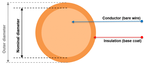
Single Wire
Litz Wire / Bundle Construction
Depending on the number of individual strands, litz wires are produced in one or more steps. Therefore, there are many options for the overall design.
Directly Bunched Litz Wires
A limited number of single wires are directly bunched so each individual wire is freely located. The single wires can take any position within the litz wire cross section.

Directly Bunched Wires
Multi Stage Litz Wires
Depending on the required strand count or performance specification, litz wires can be twisted in several steps. Any numbers of prepared bundles are stranded with each other in several twisting steps. The electrical and mechanical properties of the final product depend upon the designed litz wire construction.
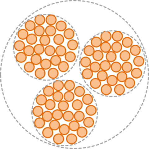
Multi Stage Litz Wire with 3 Bundles
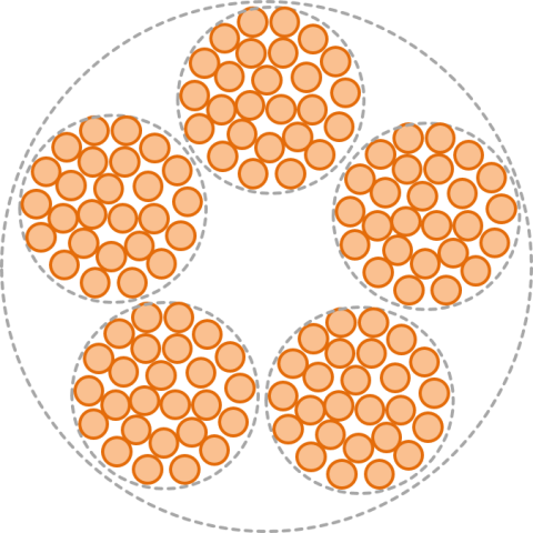
Multi Stage Litz Wire with 5 Bundles
Concentrically Bunched Litz Wires
The individual wires are positioned in one or more layers concentrically around the litz wire center conductor. In this design configuration each single wire naturally moves into its predefined position during the twisting operation resulting in consistent dimensions and working properties. A strain relief filament can be used as the central strand.

Concentric Litz Wire with 7 Single Wires
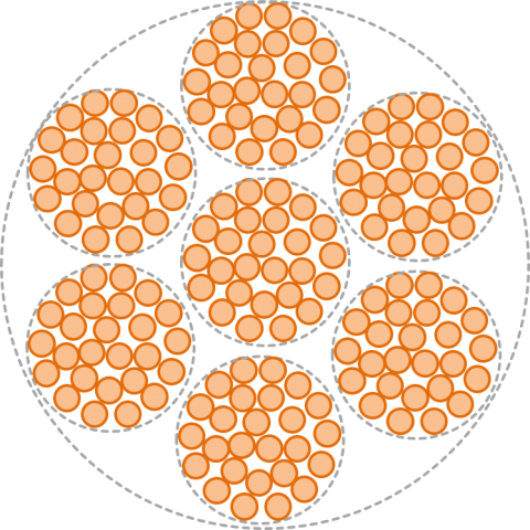
Concentric Litz Wire with 7 Bundles
Length of Lay
The length of lay describes the distance which a single wire needs for one complete rotation around the litz wire circumference (360 degrees).
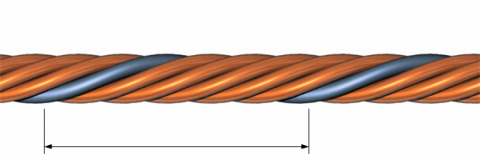
Length of Lay
Pitch Direction
The pitch direction indicates the twist or bunching direction of the bundled wire construction. Z-lay is bunched in a clockwise direction while S-lay is the opposite, or counter clockwise twist direction.

Pitch Direction S-Lay and Z-Lay
Litz Wire Types
Elektrisola offers a wide range of high frequency litz wires. Due to the different demands resulting from the broad field of applications there are several types of litz wires available.
Overview Litz Wire Types
The following table shows an overview of the basic product variations and their technical reference values. For direct comparison of features of selected product types click the link below.
Basic Litz Wire
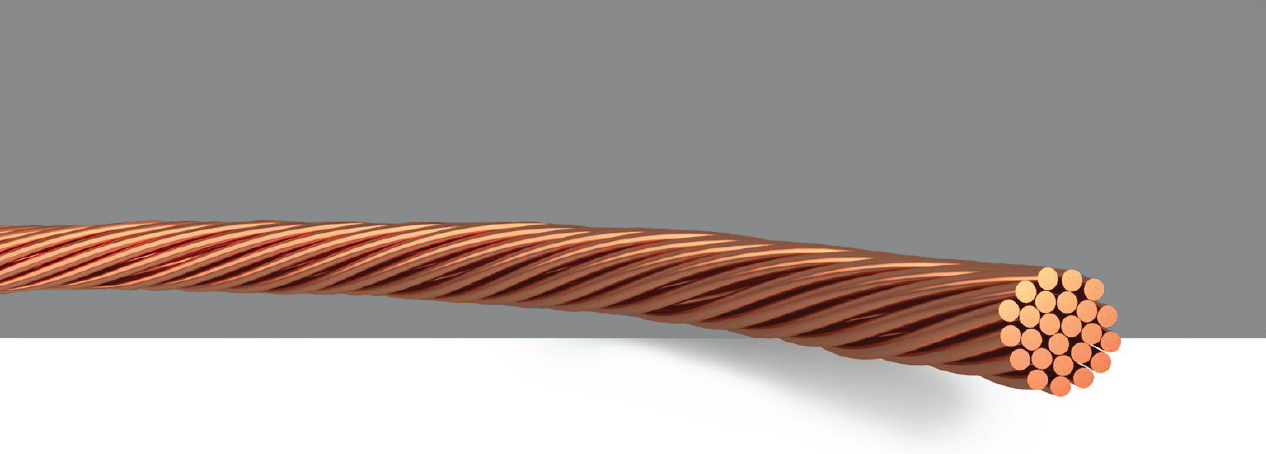
Basic litz wires are bunched in one or several steps. For more stringent requirements, it serves as the base for serving, extruding, or other functional coatings.
Taped Litz Wire
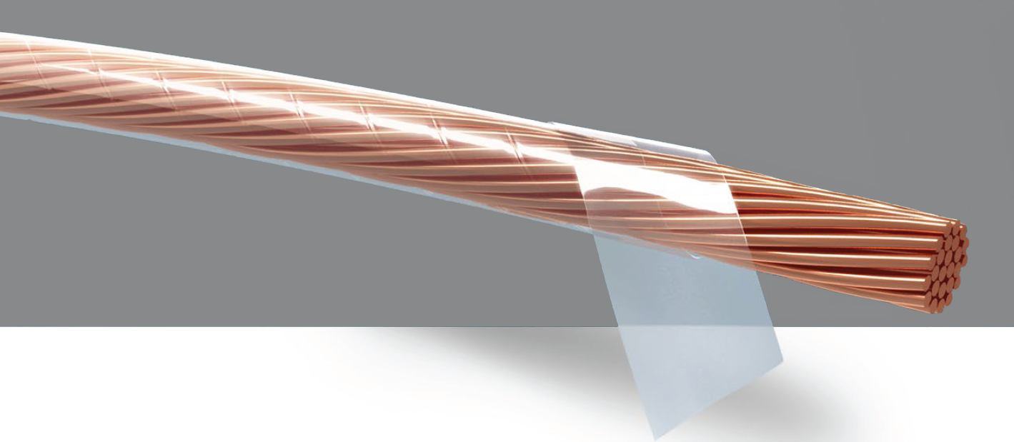
Additional insulation can be added by wrapping a tape around the basic litz wire. Increased dielectric strength, high breakdown voltage, thermal endurance as well as flexibility can be achieved by a suitable combination of taping material, number of tapes, and the degree of overlapping of the tapes.
EFOLIT®
For safety relevant applications demanding explicit certified high dielectric strength our EFOLIT ®- Litz Wire family provides reinforced insulation with at least three layers of tape. Working voltages up to 1414 Vpeak for both temperature classes F/155°C and H/180°C can be supplied. The VDE certification with manufacturing surveillance guarantees an approved and continous high performance level.
Extruded Litz Wire

Coating litz wires with extruded thermoplastic materials offers additional options for insulating litz wire conductors electrically. Extruded coatings are highly flexible and can also provide additional protection against moisture and chemical exposure.
Profiled Litz Wire
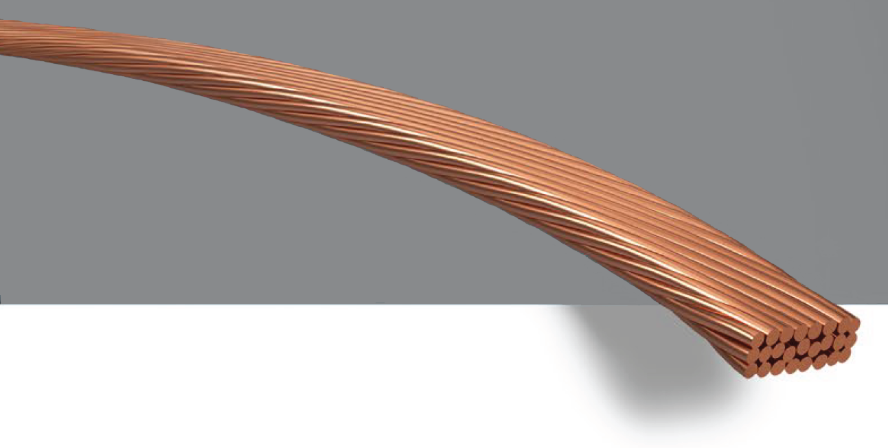
Basic litz wires and some types of served or taped litz wires can be produced with a square or rectangular cross section by a profiling process. The compacted profile provides an optimized copper filling factor for more efficient electrical properties in wound coils.
Litz Wire with Strain Relief
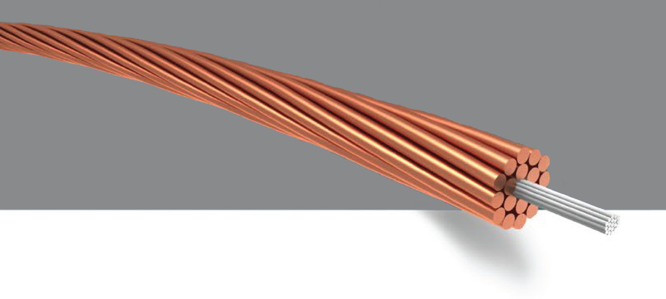
Very small litz wires or litz wires with a high demand for tensile strength or flex life performance can be reinforced with a high tensile mono or multifilament. For best performance those filaments are placed in the center of the litz wire. In some cases, it is sufficient to simply integrate the strain relief filament as a bunched non-conductive element within the litz wire.
Served Litz Wire
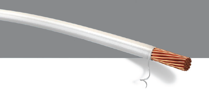
Litz wires can be spirally served with different materials such as very fine nylon or natural silk. During the serving process the litz wire is covered by the textile in one or more layers. The dimensional stability, flexibility, and impregnation performance is improved by the serving materials.
Smartbond Litz Wires
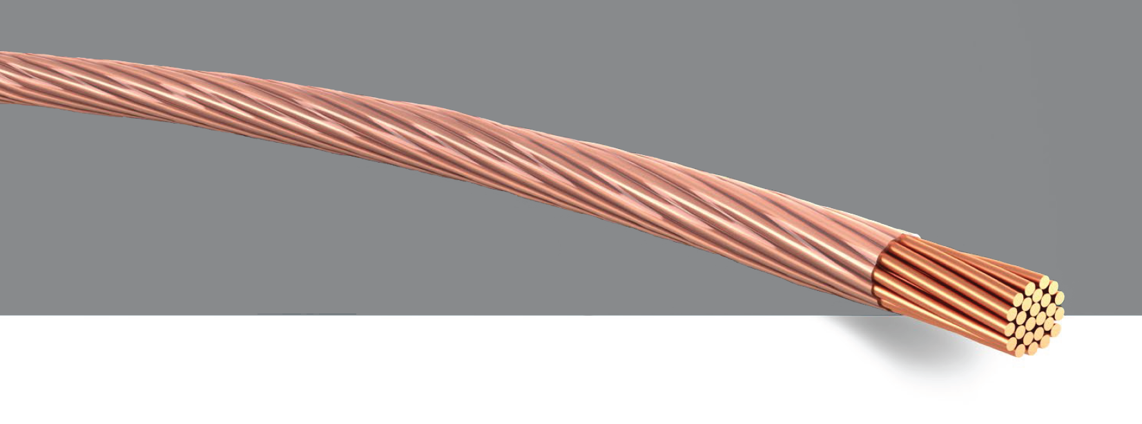
Self supporting coils can be produced with automated winding processes using litz wires provided with a 'Smartbond' adhesive. Very thin coils can be produced with Smartbond's unique self adhesive construction providing additional space for designers or to help achieve miniaturization objectives.
Dimensions
Technical Data by Dimensions
For a quick selection of an appropriate litz wire, filters can be applied to all characteristics of litz wire shown in the table underneath.
To simplify your search, you can enter min and max data for all characteristics. For example, you may enter a min and max in one column such as nominal resistance and get litz wire constructions as a result, which meet these criteria.
Other dimensions and constructions are available on request.
All data is based on EN 60317-11.
Design & Calculation
The use of litz wire for different applications is a very complex process, as it has to match best for very different technical problems. In this chapter, some basic considerations to help to design a litz wire are given.
Total Resistance of Litz Wire
The total resistance of a given litz wire construction is determined by the specific resistance of the conductor material, the nominal diameter and number of single wires, the number of bunching steps, the chosen length of lay, and additional process specific influences.
The resistance value of the single wire can be obtained from technical data provided by Elektrisola.
Using the procedure outlined in DIN EN 60317-11 the total resistance of a litz wire can be calculated as follows:
nominal value of resistance of litz wire
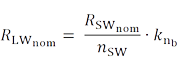
with nominal value of resistance of single wire

and number of single wires

and factor of the shortening of length due to bunching process
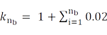
dependent on number of bunching steps

Minimum value of resistance of litz wire
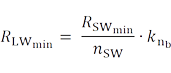
with minimum value of resistance of single wire

Maximum value of resistance of litz wire for number of single wires up to and including 25
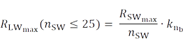
Maximum value of resistance of litz wire for number of single wires above 25
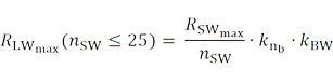
with factor for broken wires

Outer Diameter and Cross Sections of Litz Wire
The nominal outer diameter depends upon the method of twisting (directly, freely bunched or concentrically bunched), number of bunching steps, pitch direction, length of lay, and selected nominal diameter of single wires. The OD is also influenced by process specific factors.
Due to the litz wire’s natural flexibility, bending radius, and winding tension dependent dimensional stability, the nominal outer diameter is approximated by an average value in combination with a defined measuring method.
The nominal outer diameter of a bunched litz wire can be calculated guided by DIN EN 60317-11 with the following formula:
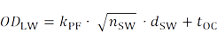
with packing factor kPF, see table below
| Packing factor KPF | |
|---|---|
| no. of wires | packing factor |
| 3 through 12 | 1.25 |
| 16 | 1.26 |
| 20 | 1.27 |
| 25 through 400 | 1.28 |
number of single wires

and nominal value for the outer diameter of the single wire

and increase in diameter by optional outer coating

The copper cross section of litz wire results from the sum of the single wire copper cross sections
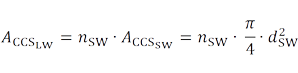
with number of single wires

and nominal diameter of bare single wire

The overall cross section of litz wire can be calculated as
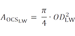
with the square of calculated outer diameter of litz wire.
Filling Factors
Litz Wire Filling Factor
The litz wire filling factor is the relation between copper cross section and overall cross section
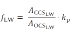
with product and process specific factor

This factor depends on the choice of nominal single wire diameter, number of bunching steps, length of lay, pitch direction, and the thickness of insulation material as well as the influence of other process parameters.
The litz wire filling factor decreases at constant total copper cross section with single wires getting finer. Since the area associated with intermediate air spaces and enamel increases disproportionately, the litz wire outer diameter and total cross section grows.
The same is true for a constant given outer diameter, since here conversely the copper cross section has to be reduced successively.
The following graphics show this relationship by means of a litz wire with constant copper cross section and several single wires of different diameter.
The graphic “Relationship of single wire, litz cross section and OD” shows the increase of OD with rising nominal diameter of single wire.
The graphic “Relationship of single wire, litz cross section and filling factor” illustrates the reduction of copper filling factor with rising nominal diameter of single wire.
By rolling round shaped litz wires to square profiles the filling factor can be further increased, see graphic “Comparison of filling factor of round and profiled litz”, green line.
In this case the closer proximity of neighbouring windings makes it possible to increase the coil filling factor once again. Use of single wire diameters thicker than 0.1 mm or 38 AWG are preferred, since litz wires constructed of finer individual wires are more sensitive to mechanical stress.
Coil Filling Factor
This factor depends on the litz wire filling factor and packing factor of the coil windings.
Optimised filling factor of a coil by using profiled litz wires can be seen in scheme below
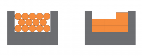
Comparison of Coil Filling Factor with Round and Profiled Litz Wire
Coil filling factor with unit [%] can be calculated as follows
with number of windings

and copper cross section litz wire

and coil winding window cross section

 Profiled litz wires as well as litz wire constructions using Smartbond have more efficient performance due to their high filling factor.
Electromagnetic Fundamentals
Calculation of High Frequency Litz Wire Losses
High frequency losses depend upon the cumulative influences of different loss mechanisms, as well as the expected working conditions of an individual application. Therefore, a simple differentiated formula-like calculation is not possible without a deeper understanding and additional tools.
Right-Hand Rule
A current I flowing through a straight conductor creates a magnetic field B, whose field lines are placed concentrically around the conductor. If a straight conductor is gripped with the right hand and the thumb points in direction of the flowing current I, then the fingers point in the direction of the circular magnet field B. The item B is also called magnetic flux density, which is proportional to the magnetic field intensity H and the material dependent magnetic permeability µ:
with magnetic field constant, permeability of free space
and relative permeability, ratio of the permeability of a specific medium to the permeability of free space

Please see the scheme “Right-hand-rule” below for illustration.
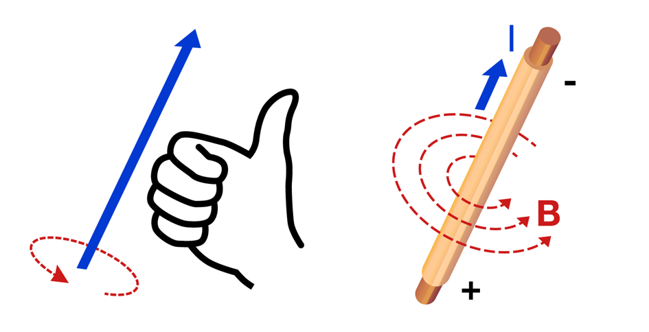
Principle of Right-Hand-Rule
Reactance / Resistance Ratio X/R
RAC/RDC
The complex resistance of a coil is defined as the impedance Z=R+jX which is a vector and consist of the resistance R representing the real component and the reactance X representing the imaginary component.
The current flows more and more along the outer surface of the conductor with increasing frequency. The measured alternating current resistance X, also referred to as RAC rises compared with the direct current resistance R, sometimes referred to as RDC. With increasing resistance values the ohmic losses through alternating current resistance rise and can even exceed the losses through direct current resistance at high frequencies.
The X⁄R ratio, sometimes referred to as RAC⁄RDC ratio describes the alternating current resistance normalized to the direct current resistance (X⁄R ≥1) and is an indicator for the high frequency performance of a litz wire. The X⁄R ratio can be measured or calculated with sufficient accuracy in most cases for a given litz wire construction and is desired to be typically between 1-12 for the respective range of frequency. Along with the correct choice of the single wire dimension, the design of the litz wire construction plays an equally important role.
The graph “Litz Wire Rac/Rdc-ratio vs. single wire-Ø and frequency” shows the calculated frequency dependent RAC/RDC trend of five different litz wire constructions with the same copper cross sectional area. It shows the alternating current resistance and the alternating current losses increase with the frequency and the thickness of single wire diameter. At a target frequency of 1 MHz the construction with 50 µm single wires has the best results. In this case, the related RAC/RDC ratio of 1.29 is still significantly higher from the optimum value of 1.0. In this case for example, a first step of improvement could be the selection of a smaller single wire diameter and/or optimization of the bunching construction.
Coil Quality Factor
The quality factor Q measures the freedom of losses of a swinging electrical or mechanical system.
As an example, a higher Q factor indicates a lower rate of energy loss relative to the stored energy of the resonator, the oscillations die out more slowly. A pendulum suspended from a high quality bearing, oscillating in air, has a high Q value. While a pendulum immersed in oil has a low Q value.
In an electrical oscillating circuit consisting of an air coil with inductance L, capacity C and ohmic resistance R, the Q factor measures the relationship between the total energy of an oscillation and its loss of energy per oscillation. An important characteristic of a high quality system is the use of a coil with high Q factor.
The basic loss factor of the coil is its resistance RL. The resistance RL increases with growing frequency, influenced by the frequency dependent skin and proximity effect.
The general relation of the quality can be described as

with different influencing factors which interfere with each other and lead to a frequency dependent trend of coil factor Q, as follows
Coil frequency f [Hz]
The Q factor increases with growing frequency and decreases again at a certain point due to disproportional rising high frequency losses and positive influence by litz wire construction features such as number of single wires, nominal diameter, and length of lay.
Coil inductance L [H]
The coil Q factor increases with growing inductance L (i.e. with increased number of windings N), the negative influence of the resulting increased coil resistance loss R compensates for this effect only at higher frequencies. The self-capacitance of the coil increases with the number of windings.
Coil Resistance R [Ω] dependent of frequency f
The coil resistance ohmic losses are influenced by the total conductor cross section ACCS. The reduction of R leads initially to an increased Q factor, but at higher frequencies comes a stronger decrease in the Q factor due to increasing high frequency losses.
Positive Q factor influence by the litz wire construction may be possible (number of single wires, nominal diameter, length of lay, etc).
The graph “Trends of quality factors Q(f)” for different planar coils shows the influence of the litz wire construction and coil construction on the trend of coil Q factor by means of three measured planar coils with 12 windings and different Smartbond litz wire constructions.
By reducing the length of lay to 10 mm, indicated as a red line in graph, the coil Q factor can be increased over the complete frequency range in comparison to the blue solid line with length of lay of 26 mm. If the increase of coil Q factor is only necessary for a selective range of frequency like in this example until 150 kHz, it can be sufficient for longer lay length to increase the coil inductance L by choosing a higher number of windings, which are in this example at a range from 12 to 17. Here the Q factor increases for the indicated range of frequency, but drops faster for higher frequencies, compare blue dotted line with red solid line.
Skin-effect and Skin depth
The current causes concentric magnetic fields, both internal and external to the conductor. In the following scheme “Principle of skin-effect and skin depth” this is presented by the magnetic field strength H.
The portion of the magnetic field within the conductor itself create concentric and interfering eddy currents which influence the current flow towards the outer surface area of the cross section with rising frequency f. Due to this effect the so called skin depth δ of the current decreases, where δ is the distance from the conductors’ surface into central direction, at which the current density has dropped to 1⁄e (e= Euler’s constant) of the amplitude value (see below). Thus the measurable ohmic resistance becomes frequency dependent and rises in value with increasing frequency. Consequently, thermic losses increase proportional to the rise of the electric resistance.

Principle of Skin-Effect and Skin-Depth
The following simplified formula describes the skin-effect only in those cases where δ is less than or equal to a third of the minimal conductor diameter and smaller than a quarter for square constructions.
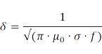
with
μ0 magnetic field constant, permeability of free space
σ conductivity of conductor material
f frequency of electric current through conductor
The table below shows the dependency of skin depth vs. frequency.
| Frequency f | Skin depth δ (Copper) |
|---|---|
| 10 kHz | 0.66 mm |
| 50 kHz | 0.30 mm |
| 100 kHz | 0.21 mm |
| 500 kHz | 0.094 mm = 94 µm |
| 1 MHz | 0.066 mm = 66 µm |
| 10 MHz | 0.021 mm = 21 µm |
| 100 MHz | 0.0066 mm = 6.6 µm |
skin depth vs. frequency
More high frequency losses are also caused by the external and internal proximity effect.
Proximity Effect
External Proximity Effect
The effect of current displacement can also be caused by the influence of external alternating magnetic fields of neighbouring conductors or other electrical components, please see the illustrating scheme “External Proximity effect”.
In contrast to eddy currents, which are induced by the skin effect, eddy currents induced by external proximity effect are not rotationally symmetric to the centre of the second conductor. The reason is the alternating magnetic field of the first conductor, which is created by an externally applied electric current through the first conductor.
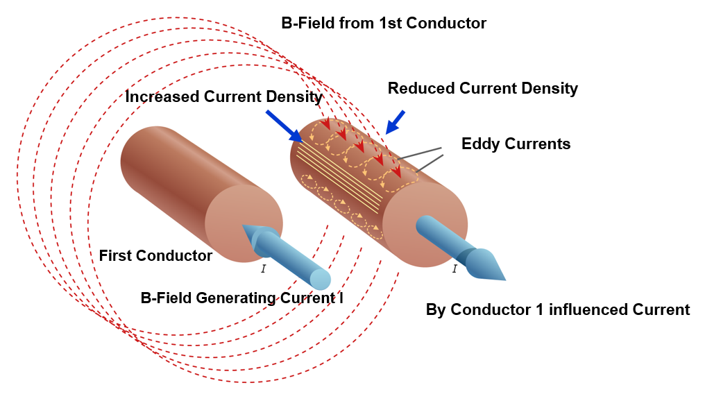
External Proximity Effect
Thus the induced eddy currents have nearly the same direction at any place on the affected conductor. The eddy currents cause ohmic losses, which lead to an apparent increase of the ohmic resistance as described in the previous section of skin effect. The necessary energy for moving these eddy currents is delivered by the causing magnetic field of the external current. Due to this general interference between eddy currents and its causing magnetic field, additional high frequency losses can also occur in any other neighbouring conductive material.
Internal Proximity Effect
The alternating magnetic fields of the single wires (strands) of a litz wire also create losses in neighbouring strands by eddy currents. Since these fields are created inside the litz wire by the strands itself, this effect is called internal proximity effect but formally seen as belonging to the skin effect, see scheme of current displacement below.
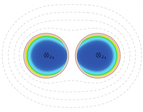
Internal Proximity Effect
As a consequence, the electrical losses of a litz wire through the internal proximity effect increase with rising frequencies and can, in certain cases, even exceed the losses of a solid conductor with the same DC resistance.
The figure “Internal Proximity effect” shows the non-homogeneous distribution of current between neighbouring single wires (current density increasing from blue to red color).
This effect demonstrates that there is an optimal range of frequency for litz wires, in which the losses are lower than for a solid conductor. Beyond this range the use of multiple single wires such as a litz wire can have negative effects.
Both the skin effect and proximity effect are the most important aspects for considering high frequency losses in electrical conductors where the combined influence of inner proximity effect and outer proximity effect is dominating. For a specified working frequency in most cases only a litz wire construction can help to reduce these losses. In this case the construction parameters such as number of single wires, single wire diameter, number of bunching steps, length of lay (pitch) and lay direction have to be specified for each application. At the same time care has to be taken that each single wire occupies each place of the litz wire cross section consistently within a defined length so each wire maintains the same length and resistance. In combination with enamelled single wires litz wires are called high frequency (HF) litz wires in this context.
Single Wire Diameter versus Range of Frequency
The design and construction of a high frequency litz wire and its resulting electrical performance depends upon many factors. Different design approaches can generate similar performance values but experience is required to correctly specify the litz wire construction that can be manufactured economically and consistently. The correct choice of the single wire diameter and number of bundles and sub bundles is therefore an important consideration for each specific application.
The table Single wire diameter vs range of frequency shows the relationship between recommended single wire diameter and frequency range.
Calculation of High Frequency Litz Wire Losses
Selection of Litz Wire Parameters
Litz wire design - following aspects are covered in this chapter:
I Litz wire features: Main influences of constructional parameters
II Selection of single wire diameter
III Selection of bunching construction
IV Example: Litz wire for HF-layer winding
V Comparison: Preselection acc. Charles R. Sullivan
I Litz wire features: Main influence of construction parameters
The performance of a litz wire is determined by its electrical, mechanical, thermal, and chemical features. While the thermal and chemical demands are fulfilled by selection of suitable insulation materials, i.e. enamel, the electrical and mechanical features depend primarily on the chosen parameters of the bunching construction.
The following table Influence of litz wire parameters on litz wire features gives an overview of the mutual influence of the construction parameters on the most important electrical and mechanical features of a litz wire.
The table Main influencing parameters for HF-coils shows an overview of litz wire criteria reduced to typical high frequency coil relevance.
Often there can be conflicting demands in each application that have to be thought fully worked out between Elektrisola and the customer. Elektrisola's expertise in litz wire design and litz wire construction coupled with the customers performance expectations for their application results in a final product exhibiting the best aspects of performance, processing ability, and cost effectiveness.
II Selection of single-wire nominal diameter
The correct choice of the single wire nominal diameter is one of the most important aspects in designing a litz wire since this directly affects the performance of the litz wire (see RAC/RDC-Ratio). At the same time, it also influences all mechanical features.
The relationship of the single wire diameter to the dominate operating frequency and the expected skin depth of the device is shown in table
In general, because of the skin effect, the higher the operating frequency, the smaller the nominal single wire diameter has to be. To consider interaction between several bundle diameters ODBundle with skin depths δ in a simplified way, the maximum single wire diameter should be smaller or equal of nearly a third of δ:

Example:
f = 200 kHz
δ ≈ 0,172 mm
ØSW ≈ 0,063 mm
Regarding the influence to the mechanical litz wire performance for equivalent total copper cross sections you can assume the following:
The smaller the nominal single wire diameter the
- more flexible and softer the litz wire
- smaller the minimal bending radius is
- better the flexlife performance
- larger the total outer diameter of the litz wire
- smaller the litz wire filling factor
- higher the single wire costs
III Selection of bunching construction
When the number of single wires is determined for the application, the specific bunching construction can be chosen. Finer litz wire with a smaller number of single wires (typical < 60) are bunched in one step, thicker and more complex litz wires are bunched in multiple steps.
The bunching construction is specified by definition of length of lay (pitch), bunching direction (S or Z), and the number of bundles and bunching steps. Proper selection of bunching parameters is required to en-sure optimum electrical, mechanical, and processing related litz wire characteristics.
Number of bundles and bunching steps
Parameters like total copper cross section, electrical resistance, or current density define the required number of single wires, which can be divided in several bundles and bunching steps. In consideration of these factors, bundles of the first bunching step can be designed for optimal high frequency performance. In consideration of these factors, the number of single wires in one bundle is typically less than sixty.
There are 4 basic bunching constructions typically used in the final bunching step: The 3, 4, 5 and concentric 7 bundle con-struction.
3, 4 and 5 bundle constructions
These bunching constructions show a good bundling performance with statistically homogeneous distribution of the single wires across the litz wire cross section. These constructions are preferred for optimal high frequency performance. The 5 bundle construction is preferred due to its round profile, since roundness increases with higher number of bundles.
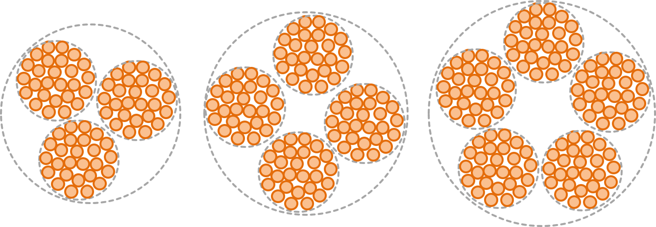
Litz Wire Constructions with 3, 4 and 5 Bundles
Concentric 7 bundle construction
These concentric constructions, also called “1+6 bundling”, show both high flexibility and good dimensional stability and roundness. One bundle always runs centrally, so this construction is less suitable for applications with demand for optimal high frequency performance due to the difference in total resistance between bundles. In order to compensate for differences in bundle lengths for the final bunching step, the pitch direction of the central bundle is opposite to the direction of the concentric outer bundles. Therefore, the pitch direction of the central bundle always represents the pitch direction of the final bunching step.
The previous basic constructions can be combined with each other independently from the number of bunching steps and complexity of electrical and mechanical demands. Special constructions are possible.
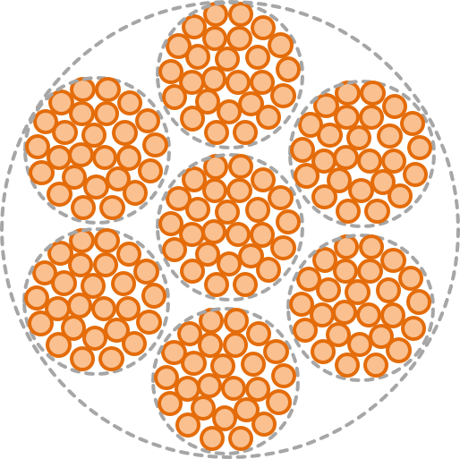
Litz Wire Constructions with 7 Bundles
Selection of length of lay and pitch direction:
The length of lay determines the mechanical compactness and the high frequency performance of a bundle. A measure for the tightness of a bunching step is the so called bunching factor. It proportions the length of lay to the outer diameter of the bundle and is typically in the range of 15 mm -20 mm:
Bunching factor
The bunching factor fB can be calculated as follows

Depending upon the pitch direction, the bunching factor for pre-bunching steps is often chosen higher in many cases.
For the selection of length of lay and pitch direction the following basic statements can be assumed:
The smaller the length of lay,
- the more compact, stiffer, and more dimensionally stable the construction
- the larger the outer diameter of the bundle
- if optimal high frequency performance is demanded, an optimal combination of aligned pitch directions for all bunching steps must be chosen
- counter rotating pitch directions of multiple bunching steps are to be preferred for complex litz wire constructions, where high mechanical flexibility is demanded
- for wound coils the length of lay should be in the range of the smallest winding diameter
The table Optional litz constructions and features shows an overview of different designs of a litz wire 270 x 0.071 mm and its features.
IV Example: Litz wire for high frequency layer winding
In many cases high frequency coils are layer wound with a small number of windings. Usually those litz wires are served with silk or nylon, since exact winding in layers is only possible with litz wires which keep their round shape on the coil bobbin also with applied winding tension. In some cases also unserved litz wires basic litz wires can be used. Here special attention is required to select solid and dimensionally stable constructions. Nevertheless, since small elliptical deformation is not avoidable, this has to be compensated by reducing the total outer diameter appropriately. For this reason, with a given maximum outer diameter in this case a served litz wire can show a higher copper cross section than a non-served construction.
Example
An example shows the simplified preselection of a litz wire construction for a layer winding with 30 windings and an operating frequency of 200 kHz. Assumed is a winding window with an effective usable size of width by height: 25.8 mm x 8.0 mm.
Layer construction
Depending on winding technology, layer windings can be constructed in layers with equal or alternating number of windings. For preselection it is possible to roughly calculate with the same number of single wires per layer. This results in 3 layers with 10 windings each for the winding window, and a calculated max. outer diameter for the processed litz wire of dLW=25.8 mm ⁄ 10 = 2.58 mm.
Single wire diameter
The higher the applied operating frequency the smaller the single wires will become. At the same time the costs for the single wire will increase with smaller nominal diameter dSW, as well as for the bunching process with increasing complexity of the bunching construction. Regarding the interaction between the thickness of the sub-bundles and the frequency dependent skin depth δ the ratio dSW ≤ δ/3 can be taken approximately as indicator for the choice of the nominal single wire diameter. In practice it represents a working compromise between frequency performance and costs. Depending on application and technical demands also variations are allowable and common.
In this case a nominal diameter dSW = 0.063 mm is sufficient for a first approach (see example above, section II).
Bunching construction
The total outer diameter of a litz wire depends on the dimensional stability of the individual wires bunched during the winding process. To take this into consideration as empirical value the calculated maximum outer diameter of the processed litz wire dLW=2.58 mm, see above, should be reduced by 10% to dSW=2.32 mm for the serving material and by 15% to 20% to dSW=2.19 mm for the non-served construction.
The non-served litz wire should be bunched compactly, for example that means a small lengths of lay and same pitch direction per bunching step. Constructions with 4 bundles or 5 bundles are preferred.
The table Litz wire design for a HF-coil with specific winding window shows a comparison between suitable served and non-served litz wire constructions for operation frequencies of 50 kHz,125 kHz and 200 kHz and a winding window of width x height = 25.8 mm x 8.0 mm.
In this case, for the desired layer winding
- Copper filling factor of served litz wire is a little bit smaller compared with the basic litz wire. The number of single wires and thus the total copper cross section of the unserved litz wire still increases.
- Copper filling factor of the winding window lies typically in the range of 25% to 30%. It is higher for the served litz wire compared with the unserved basic litz wire due to its higher total copper cross section.
- A construction with 5 bundles enables a symmetrical litz wire structure with sub bundles of significantly less than 60 single wires.
If layer winding is not necessary and a randomly wound coil can be used, it is possible to produce a very flexible and soft litz wire. In this case the coil windings cling to each other, intermediate spaces are filled optimally and thus the copper filling factor of the winding window can be increased once again. Alternatively the usage of profiled litz wires is possible as well. It is also important to ensure that the copper cross section of the design allows for the required current capacity of the application to be achieved.
V Comparison: Preselection acc. to Charles R. Sullivan
Another method of simplified preselection of litz wires for RF coils is proposed by Charles R. Sullivan from the Thayer School of Engineering in Dartmouth, USA in his study Simplified Design Method for Litz Wire.
The parameters used are the skin depth, operating frequency, number of windings of the winding window, the width of the winding window, and from this calculated constant k is required. This method then proposes a number of suitable litz wire constructions consisting of nominal single wire diameter, a maximum number of single wires for the first bunching step, and the number of bundles for any further bunching step.
This is accomplished in the following steps:
1. Determination of the skin depth δ calculated from the specific conductor resistance ρ, operating frequency f and the permeability µ0.
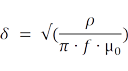
2. Definition of available width bW of the winding window and the requested number of windings NW of a given coil construction. As an option, construction with an air gap can be considered.
3. Calculation of approximate values for the recommended total number of single wires nSW depending on several nominal single wire diameters dSW. The effectively applied number of single wires for a specific nominal diameter can deviate from the calculated value up to ± 25 %.
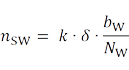
4. Selection of single wire nominal diameter and number of single wires is made. Following this selection, a determination is made as to which of the tabular single wire diameters (and number combinations) according to a given number of windings fits into the winding window. A winding window copper filling factor range of 25% to 30% is assumed. Demands regarding litz wire resistance and current capacity have to be determined. Alternative constructions with bigger single wires are also possible.
5. The interaction between skin depth and bundle diameter is taken into account: Calculation of the maximum number of single wires nSW1max of the first bunching step is dependent upon the frequency influenced skin depth δ and the chosen nominal single wire diameter dSW.
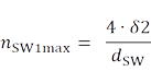
6. A part of the calculated total number of single wires, see (3), on several bunching step combinations of 3, 4, and 5 bundle constructions.
A recommendation of certain bunching lengths or bunching directions of the constructions is not given in this context. It is left to the litz wire manufacturers.
The linked table Comparison of design approaches compares the previously given practice-related selection of Elektrisola`s typical constructions with those according to the method of Ch. R. Sullivan. It is related to a layer wound coil and a winding window of 25.8 mm x 8 mm and operating frequencies of 50 kHz,125 kHz and 200 kHz.
The table shows that the litz wires, selected with the practice-related approach, correspond closely with those constructions selected with the Sullivan-method. They cover implicitly the recommended basic features:
- the total number of single wires of the practice-related samples lies within the range suggested by the Sullivan method.
- the combined application of 3, 4 or 5 bundle constructions are an integrated part of Elektrisola typical litz wire designs (see table 5).
- the single wires of the basic bundles in the first bunching step are independent from the respective construction and Elektrisola-typical free selectable within a number of 60 single wires (see table 5).
- cost reductions are possible with thicker single wires (dSW≤ δ/3) designed constructions (see table 5), which show that the Sullivan recommended ideal basic bundling of ≤ 64 to 36 single wires.
- apart from cost reduction these constructions can additionally increase the filling factor of the litz wire and of the winding window (see table 5).
- Through careful selection of bunching length and direction, the product can be optimally specified for each unique application
Therefore, Elektrisola's applied design concepts for high frequency litz wires typically include both practical and theoretical requirements.
Processing of Litz Wire
Connection Technologies for Litz Wires
The connection technology of litz wires often poses a challenge. The table Connection Technologies advises the connection technologies which are generally applicable. Only the most important factors of influence have been classified. Many others, such as enamel type and insulation thickness of the single strands, heat resistance of the additional insulation, the stranding construction (tight/compact or wide/flexible), have been left unconsidered.
Please contact us if information on connections to alloy litz wire is needed or for any other questions.
Determination of Winding Tension on Litz Wire
The table Max. winding tension on single wire strands shows the recommended maximum winding force. The maximum feasible tension for litz wires can be calculated by multiplying the number of single strands by the appropriate winding tension of the single strand. Regardless of this calculation, for litz wire diameters thicker than 5 mm, tension limits of (420 N) for hard metals and (270 N) for copper and soft metals are recommended.
These values are guidelines and can deviate significantly depending on the manufacturing process.
Spools
A wide variety of spools and packaging materials designed specifically for each spool type is available. The selection of spools is made in close cooperation with the customer taking into account the customer’s production process and the availability of spool types.
There are specific types of spools for wire in the Western World, i.e. Europe and America, and in the Asian World.
Available types of spools can be taken from succeeding tables.
Applications
Elektrisola supplies high frequency litz wire for the following applications including certifications and requirements in accordance with the standards of each sector.
1. Automotive
In response to an increasing global demand for zero emission vehicles, automotive companies have made huge investments in the development of electric cars. ELEKTRISOLA was the logical choice as an early partner in the development of innovative EV charging components, providing technical support and litz wire to today’s major suppliers. Today, development efforts continue as relentless demands for faster charging times and increased efficiency require imaginative litz wire solutions.
1.1 EV components containing litz wire
- On-board charger (OBC)
- DC/DC converter
- Wireless charger (WC)
- Charging station
- Electric traction motor
Litz wire is necessary for the listed components to reduce copper losses at higher frequencies in order to increase efficiency.

Higher power densities are possible due to the efficiency improvements from the use of high frequency litz wire. Lighter and cheaper constructions are able to be used which lead to increased battery range for electric vehicles. In addition, cheaper production through material savings is also possible.
Elektrisola offers a wide range of litz wires, which are core materials and determining factors of several electric vehicle components, described in the following chapters.
1.1.1 On-Board-Charger (AC/DC)

The On-Board charger (OBC) transfers the power from the grid into the traction battery. The charger converts the alternating current to direct current which flows into the battery.
If charging from an external high voltage DC charger for very fast charging, the On-Board Charger is bypassed.
The input voltage is the result of the structure of the local grid according the following considerations:
| Input Voltage (worldwide) | |
|---|---|
| 85V - 275V | 1-phase AC |
| 400V | 3-phase AC |
| Output Voltage | |
| 170V - 800V | DC |
Technical Details of the On-Board-Charger
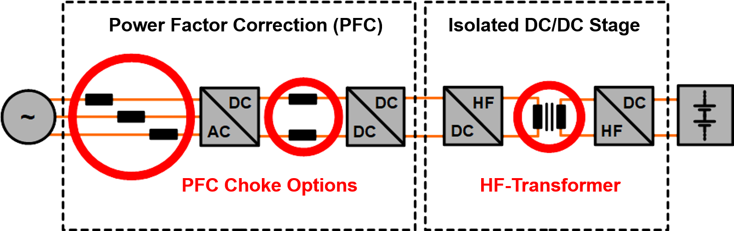
On-Board Charging System
The on-board charger primarily consists of the power factor correction stage (PFC) and the DC-DC converter stage, shown in the figure above.
Before and after the stages two noise filters for electromagnetic compatibility (EMC) are applied.
Power Factor Correction Stage
The PFC stage ensures a sinusoidal current consumption from the public electrical grid.
A boost converter fulfils the power factor correction.
The relevant element for efficiency in this stage is the high frequency coil, which can be realised as a single or dual coil, depending on topology.
The switching frequencies are typically below 50 kHz.
Elektrisola can optimize all litz wires meant for the usage in OBC with the target to achieve the highest efficiencies.
High Voltage DC-DC Converter Stage
The main converter transfers the energy through a galvanic isolated transformer. This high frequency transformer is the key element of the OBC. It transfers the pursued power from primary to secondary side through the air gap, with the highest possible efficiency.
Inductive High Frequency Components
High Frequency Coil for Power Factor Correction
This coil is a central element in the boost converter. The switching frequencies are up to 50 kHz, depended on the converter topology.
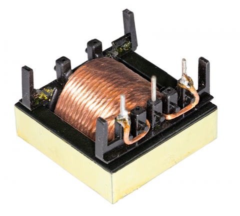
PFC Choke with Taped Litz Wire
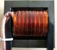
PFC Choke with Reinfoced Litz Wire
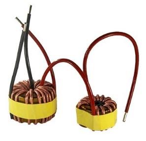
HF Transformer and PFC Choke, coiled with Taped Litz Wire
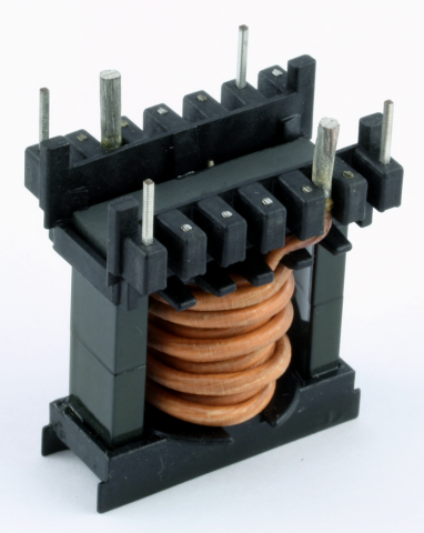
PFC Choke with Reinforced Litz Wire
Design options of litz wire products for high frequency (HF) coils can be seen in the following links:
- “Basic”
- “EFOLIT”
- “Taped”
- “Served”
High Frequency Transformer with Galvanic Separation
The transformer consists of at least two coils for primary and secondary side.
The galvanic separation is realised by a conversion from electric to electromagnetic energy transmission. Thus, the power is transmitted over the air gap without mechanical connection.
Galvanic separation is required for electric vehicles to hold the grid potential separate to the vehicle potential due to safety concerns.
A combination of several insulation materials with specific air and creepage distances ensure a predetermined level of breakdown voltage protection.
HF transformer design examples:
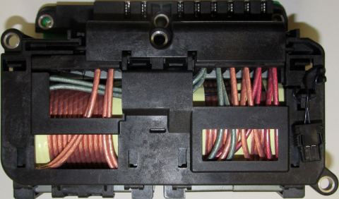
HF Transformer with Two-Chamber Bobbin
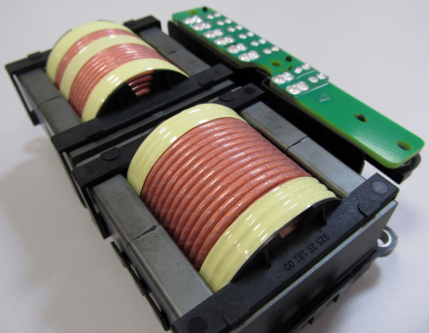
HF Transformer with Two-Chamber Bobbin
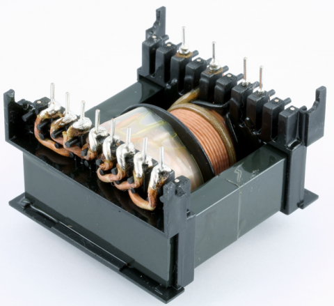
HF Transformer with Intermediate Tape Insulation
HF Transformer with Served Litz Wire and Intermediate Tape Insulation
For high voltage applications with high safety demands, Elektrisola offers the VDE-certified EFOLIT product family.
The following product links show a general overview of optional litz wire types for high frequency transformers:
- “EFOLIT”
- “Taped”
- “Served”
- “Profiled”
1.1.2 DC/DC Converter
General

Electric Vehicle with HV-LV DC/DC Converter
Electric vehicles have at least two different voltage networks, one with a low voltage battery for all automotive peripherals and another with a high voltage battery for drive train components. The DC/DC converter ensures the bidirectional energy transfer between both networks by voltage conversion with galvanic separation.
Technical Details of DC/DC Converter
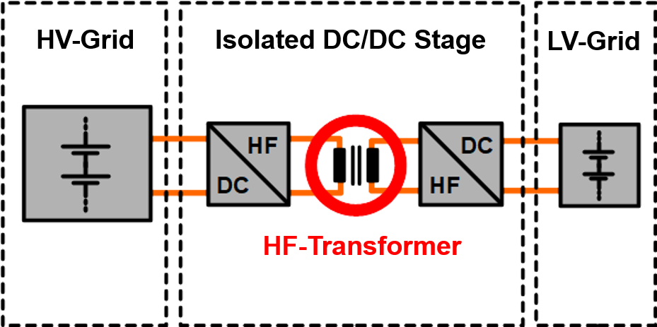
High Voltage / Low Voltage DC/DC Converter System
The low voltage EV network is typically based on lead acid batteries with voltage levels between 12 V and 48 V.
The EV high voltage network often includes a lithium based battery and the voltage level varies between 200 V and 1000 V.
Typical power of DC/DC converters is between 1.5 kW and 5 kW.
The power electronics typically use soft switching topologies with a resonant transformer stage with galvanic separation. Bidirectional energy flow is realised by buck/boost topologies between the two stages.
Inductive High Frequency Components
The efficiency of the DC/DC converter is the key to ensure a minimum construction volume and low weight. High switching frequencies help to reduce inductor and transformer sizes. Modern semiconductor technologies make higher frequencies possible, which enables even smaller inductors and transformers.
The switching frequencies range from 100 kHz to 550 kHz. The High Frequency litz wire products are optimised for the application to guarantee high filling factor for high efficiency while also maintaining high voltage durability.
Widely used diameter of single wire strands is 0.05 - 0.1 mm.
Typically values of temperature class varies between B(130°C) and F(155°C).
Litz wire products with taping, extrusion and serving are common.
Which one to choose depends on the individual application parameters e.g., available space and breakdown voltage requirements.
See examples of HF transformers in the following pictures:
HF Transformer with Intermediate Tape Insulation
HF Transformer with Separating Winding Barrier
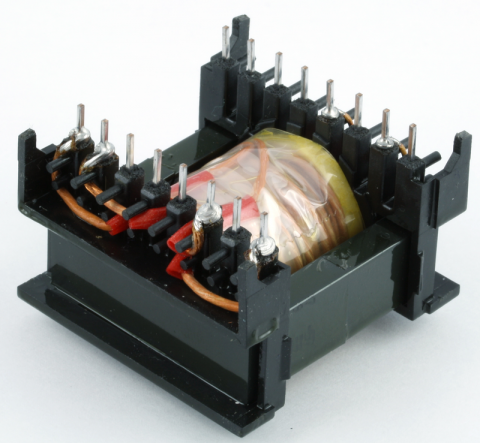
HF Transformer with Reinforced Litz Wire
1.1.3 Wireless Charger
General

Electric Vehicle with connected Wireless Charger
Wireless charging (WC) or inductive charging (IC) is one type of several wireless power transfer (WPT) methods. It is very comfortable way how to charge an electric vehicle, because the power can be transmitted over large air gaps without any cable connection at high efficiency factors.
The charger uses two planar inductor coils to transmit the energy via a time varying electromagnetic field.
There are two basic different types of wireless charging:
Static Wireless Charging
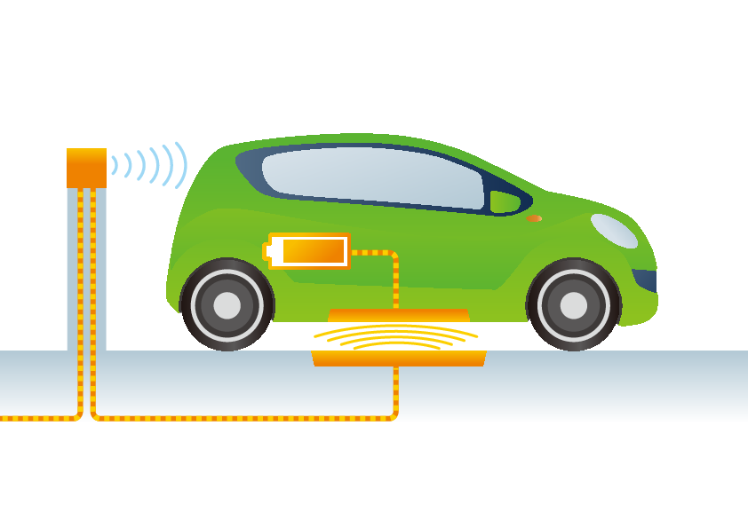
Principle of Static Wireless Charging
The vehicle is charged while it remains parked. The receiver coil is fitted on the bottom of the car and the transmitter is fitted on or in the ground. For the charging process the receiver has to be aligned over the transmitter during the parking process.
Dynamic Wireless Charging
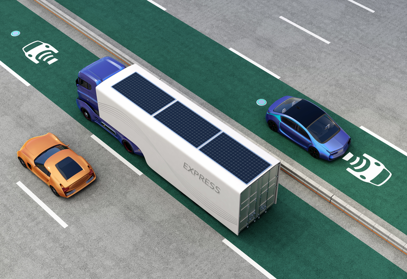
Principle of Dynamic Wireless Charging
With this future technology the vehicle receives power while in motion above a line of several stationary transmitter pads.
Technical Details
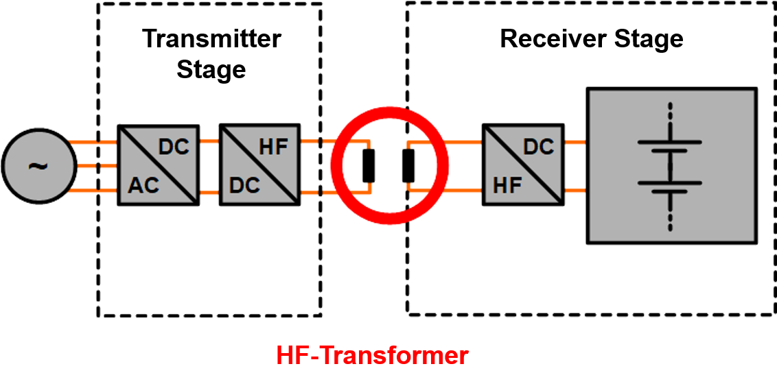
Wireless Charging System
There are two main types of inductive charging:
Inductive Wireless Charging (IWC), also called Inductive Power Transfer (IPT)
The principle of IWC is “Faraday´s law of induction” and was first used in the 18th century. The first electric vehicle was powered by IWC in 1970s.
Similar to the on board charger mentioned above, the first stage of the charger is a PFC stage to ensure sinusoidal current consumption.The wireless transmission of power is realised by mutual induction of the magnetic field between the transmitter and receiver coil. In the primary coil a time varying magnetic field is created by alternating current which induces a voltage on the secondary side and moves electrons through. Subsequently a current flows through the secondary coil where the AC current is rectified and filtered to charge the traction battery.
Since the voltage is only induced when the magnetic field changes, a rapidly alternating current is required. Typical operating frequencies of IWC lay between 20 and 90 kHz.
IWCs operate like a transformer with an air coil instead of metal core.
Resonant Inductive Wireless Charging System (RIWC)
A resonant operated coil is much more efficient, because the impedance decreases at a resonance frequency. As a result, the quality factor is very high, for details see Electromagnetic fundamentals.
Furthermore, with resonance operation, the power can be transferred over longer distances. Weaker magnetic fields can transmit as much power as IWC designs.
For maximum power transfer the resonant frequencies of the primary and secondary coil should be matched. Additional compensation circuits are added to the coils. These electric circuits improve the efficiency further.
Typical operating frequencies of RIWC is between 10 kHz to 150 kHz.
Standards for wireless charging
SAE J2954, set by the Society of Automotive Engineers, defines WC for Light Duty Plug In EVs and Alignment Methodology. See the following table for further detail:
| Power Classes for WPT according to SAE J2954 | ||
|---|---|---|
| Class | Power [kW] | Frequency band [kHz] |
| WPT 1 | 3.7 | 81.39 - 90 |
| WPT 2 | 7.0 | 81.39 - 90 |
| WPT 3 | 11.0 | 81.39 - 90 |
In development, charging powers of 50 kW are common. For heavy duty applications, multiple 50 kW chargers are combined to reach up to 500 kW per vehicle.
Furthermore, SAE J2954 predefines a minimum efficiency of 85 % when the coils are aligned properly.
The necessary galvanic separation is implied by the wireless transmission, where the transmitter functions as primary coil and receiver as secondary coil.
Different air gap distances are classified according to the following table:
| Alignment Methodology for WPT according to SAE J2954 | ||
|---|---|---|
| Class | Distance [mm] | Frequency band [kHz] |
| Z Class 1 | 100 - 150 | 81.39 - 90 |
| Z Class 2 | 140 - 210 | 81.39 - 90 |
| Z Class 3 | 170 - 250 | 81.39 - 90 |
Requirements for Planar Coils with Litz Wire
- Single wire
Typical litz wire constructions are based on single wire strands with diameters between 0.030mm and 0.071mm
- Temperature class of the single strand
Temperature of the coil should not exceed 100°C, therefore low temperature classes for the single wires are sufficient.
- Litz insulation
Due to high voltages, tapes are often used.
- Profiled litz wire
The coils are wound as planar coils to distribute the magnetic field strength to a homogeneous density.
Profiled litz wire is a common way to maintain a high filling factor while maintaining the well distributed magnetic field.
1.1.4 Charging Station (AC/DC)
General
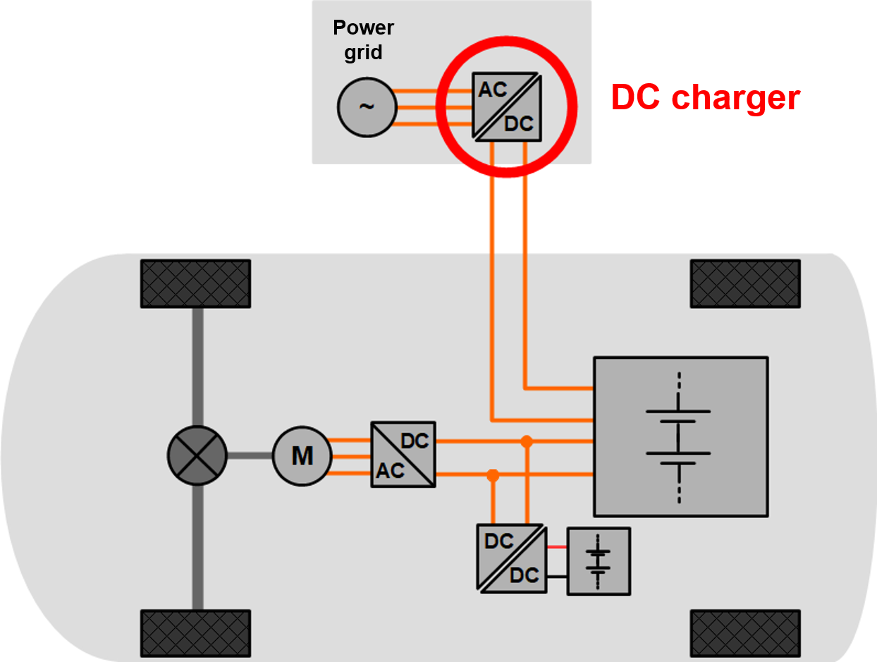
Electric Vehicle with connected DC Charger
Charging stations supply electric energy for the recharging process of the traction battery of plugin (H)EVs. Therefore, two different kinds of charging stations are available to convert AC from the power grid into DC for the EV battery:
Multiple Charging Stations
AC charging station, which acts as energy source for the OBC.
DC charging station, which acts as direct energy source for the EV battery. The charger hereby is part of the charging station.
Technical Details of Charging Stations
AC charging station
For the AC charging process, the chargers are installed on board the electric vehicle (OBC), and details are described in chapter 1.1.1. A special version of AC charging stations are wireless chargers, which are described in chapter 1.1.3.
The on-board charger can be plugged in for electric power connection at either public charging stations or residential charging stations.
Public Charging
Public charging stations are often combined with public parking lots. They are owned by commercial or private ventures, sometimes in partnership with a parking lot owner. The following table gives an overview of the different charging stations.
| AC charging options at public charging stations | |
|---|---|
| Type of Plug | Voltage / Power |
| Type 1 | 120V / 1.92kW or 240V / 3.8kW, 5.8kW, 7.2kW |
| Type 2 / Combo 2 | 400V / 3.6kW, 11kW, 22kW, 43kW |
Residential Charging
Residential or private charging stations, often referred to as “wall box” chargers are home charging stations, which can be installed at private facilities by an EV owner to charge the vehicle at home, but they are often limited by output power as either higher voltage sockets are not available or the current is limited.
A comparison of different charging options can be seen in the following table:
| AC charging options at residential wall boxes | |
|---|---|
| Type of socket | Voltage / Power |
| Domestic Socket | 120V / 1.4kW |
| 230V / 2.3W, 3.6kW | |
| 400V / 11kW, 22kW, 43kW | |
DC Charging Station
Charging Station with Type 2 Plug
DC charging stations can achieve power higher than 43 kW because there is no limitation on space and weight inside the charger, as it is the case with the OBC installed in the vehicle.
The charger is integrated into the DC charging station, while the power electronic technology in external chargers is the same as in OBC.
Often modular constructions are used in DC chargers. Thereby the power can be easily increased by adding modules in a parallel circuit to the charging station.
A comparison of different charging options can be seen in the following table:
| DC charging options at public charging stations | |
|---|---|
| Type of Plug | Voltage / Power |
| CCS combo 1 | < 500V / <80kW |
| Type 2 / Combo 2 | 200-1000V / < 350kW |
| CHAdeMO type 2 | 500V / <62.5kW |
| CHAdeMO type 2 | 1000V / < 400kW |
| Tesla Super-charger | 480V / < 250kW |
Inductive High Frequency Components for Charging Stations
For future types of EVs, the industry is planning for charging power up to 450 kW with voltages at 800 V. State of the art technology in power electronics development make voltage levels up to 1000 V possible. These high voltage levels allow for faster and more efficient charging.
These trends lead to high requirements with regard to the insulation of high frequency litz wire in the inductors and transformers of the chargers.
External DC chargers, in comparison to on-board chargers, can supply higher charging power, as the available space is not limited. On-board charging power is limited by weight and space of the components.
Typical litz wire constructions of high frequency transformers in DC chargers use single wires of 0.07 - 0.1 mm diameter, optimised for switching frequencies between 50 and 100 kHz.
1.1.5 Electric Motor
General
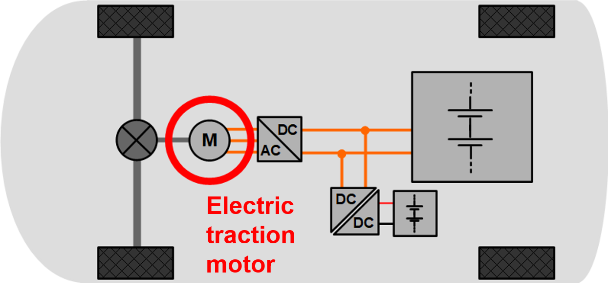
Electric Vechicle with Electric Traction Motor
Electric motors are the core of an EV drive train. A great advantage of electric motors is the high torque available from zero speed over the entire range of speeds.
Electric motors already have high efficiencies compared to internal combustion engines (ICE), but still have potential for efficiency optimisation. The motor is driven by an inverter with high power at switching frequencies up to 50 kHz. The resulting copper losses in the coils can be decreased by using high frequency litz wire instead of traditional single wire constructions.
Many different motor concepts exist, which vary in electromagnetic principle but also in mechanical construction and different drive train concepts.
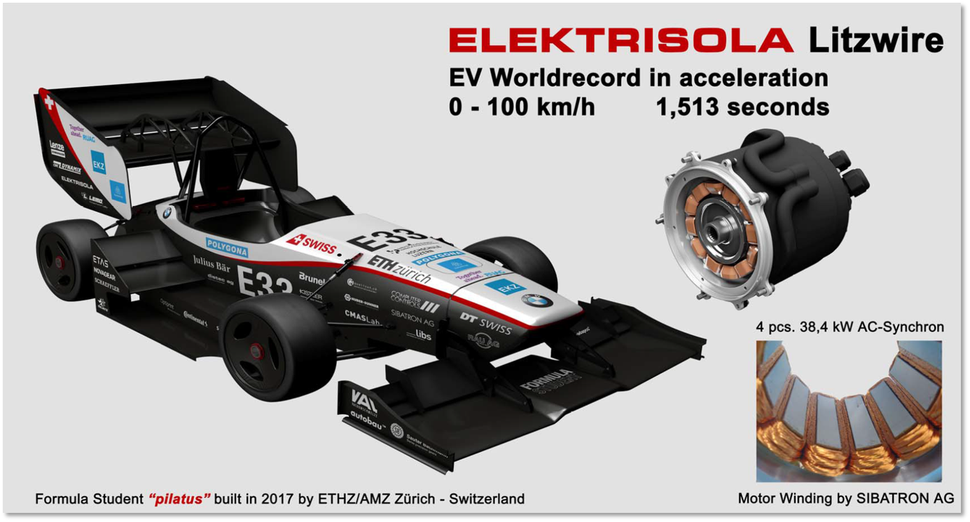
Formula Student Racer with Electric Traction Motor
For electric mobility, motors have to be chosen according to the automotive requirements. The main target is to increase the power density, which leads to higher economic efficiency throughout the EV life cycle.
World Solar Challenge Racer with Electric Traction Motor
Formula Student Racer with Electric Traction Motor
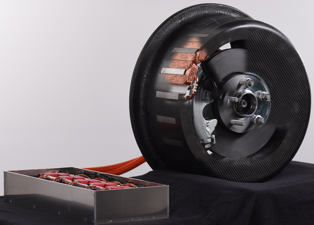
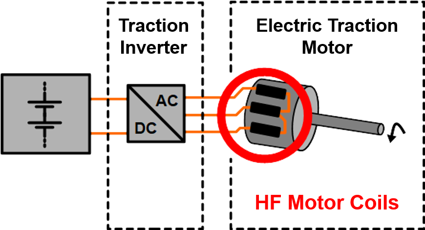
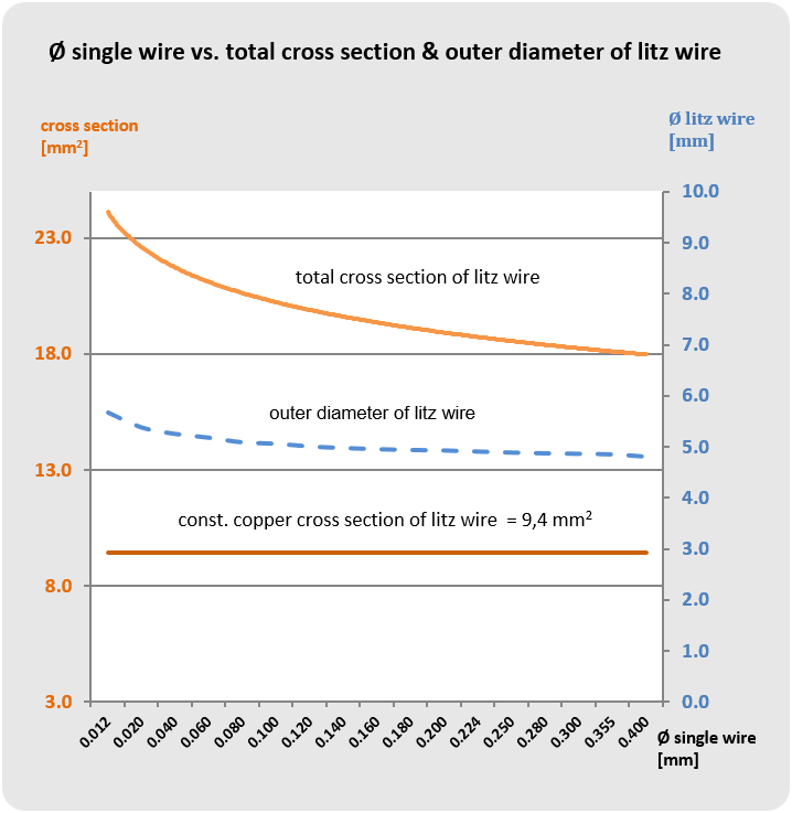
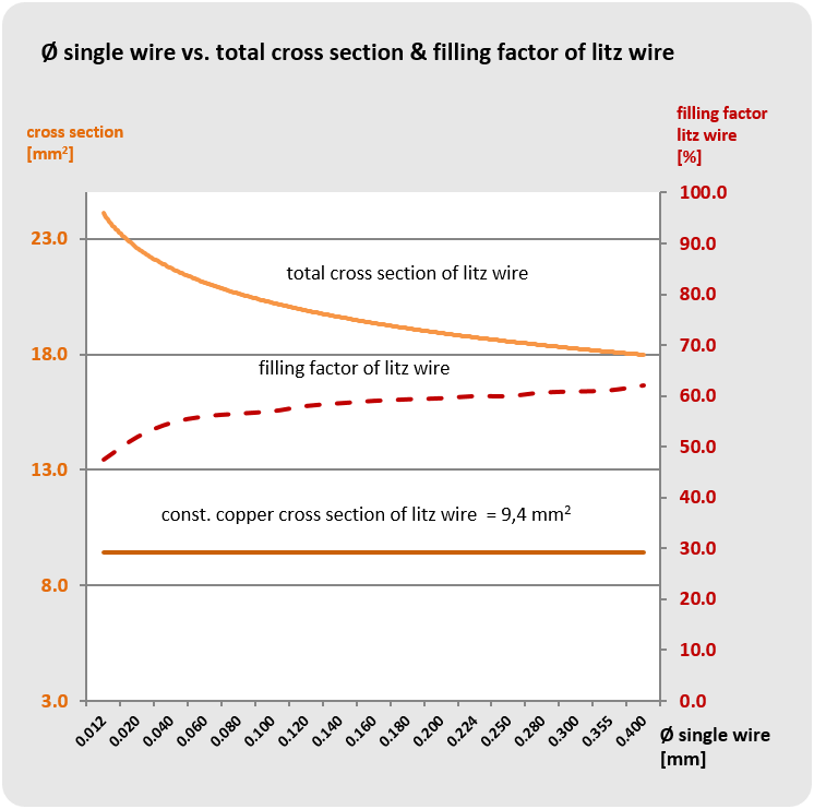
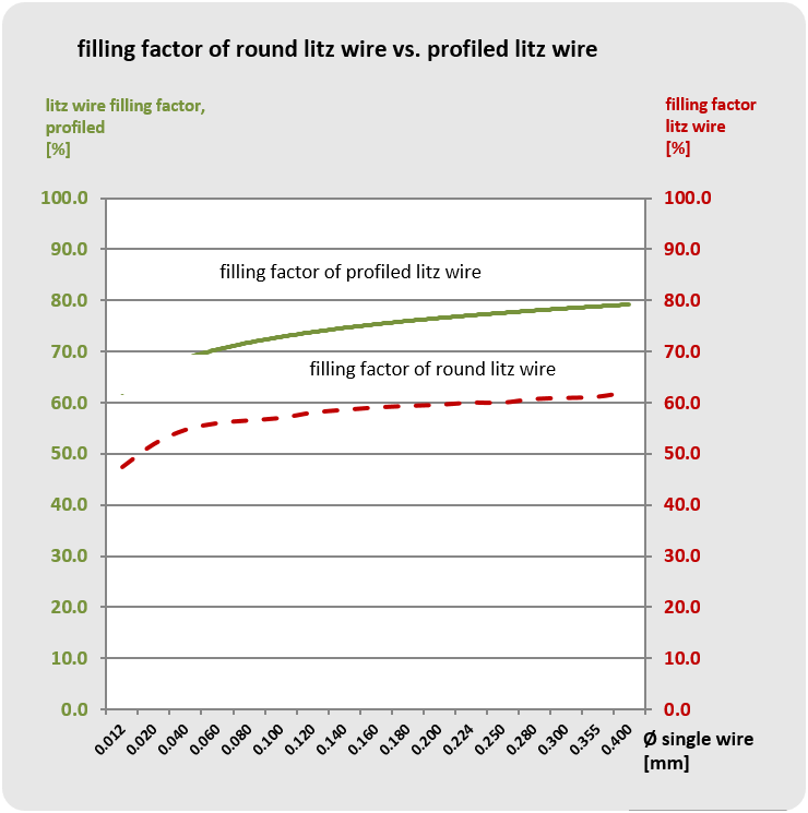
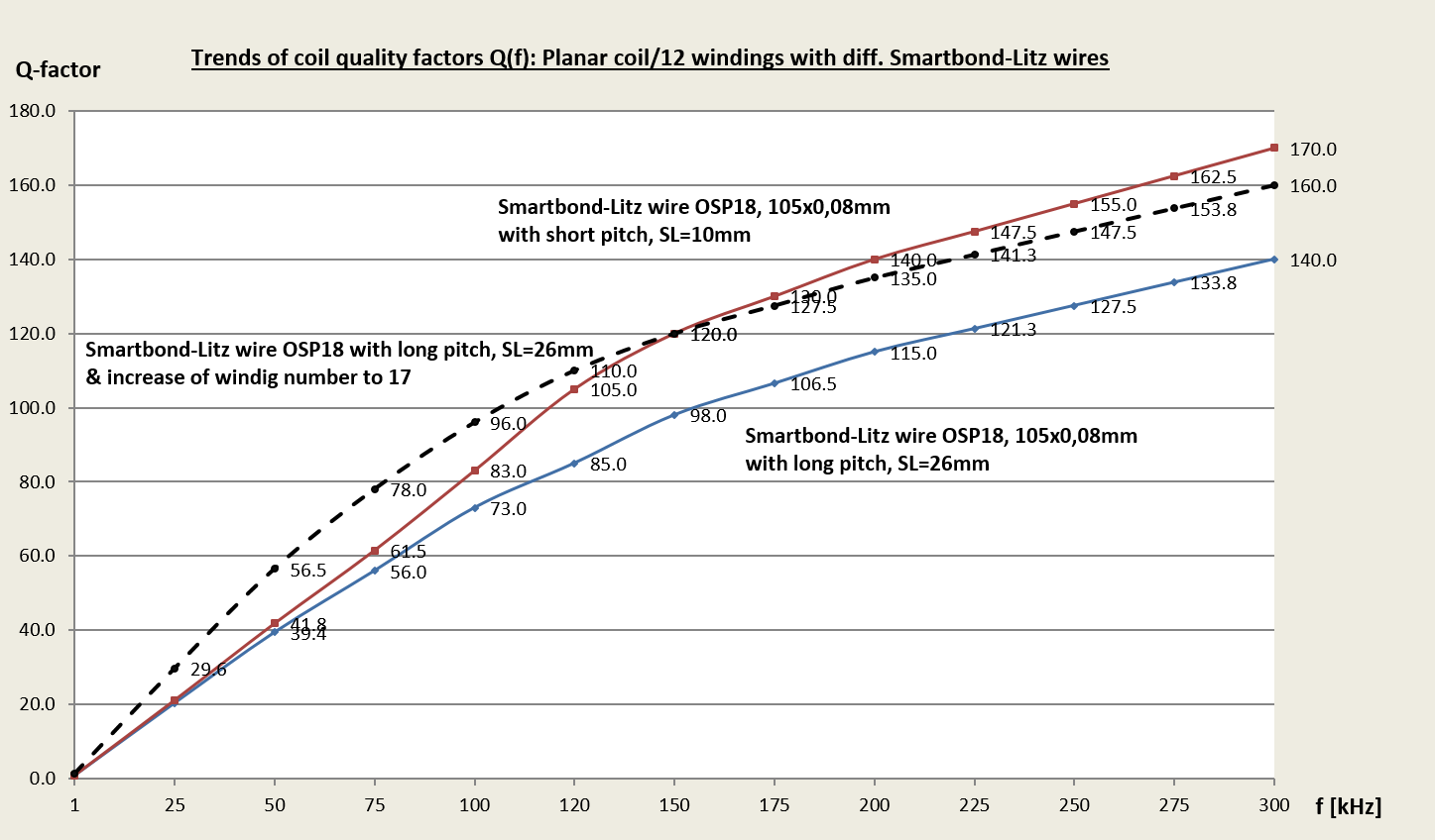
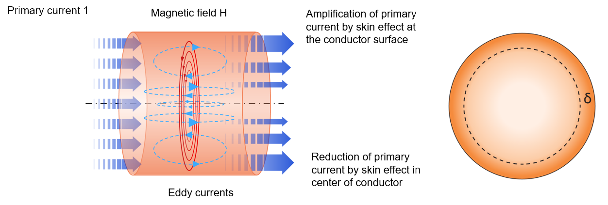
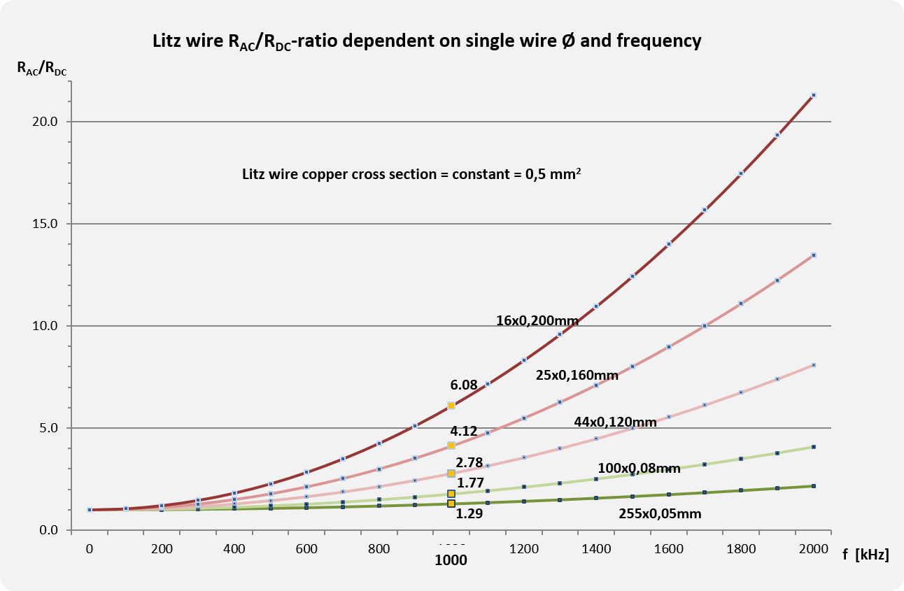
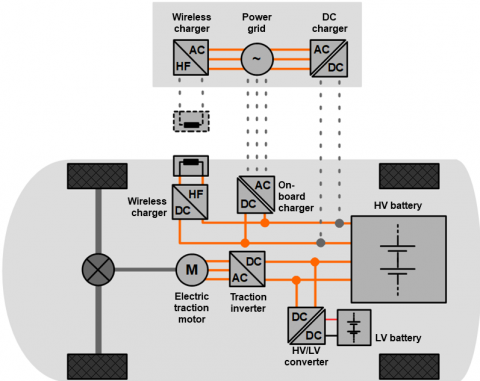
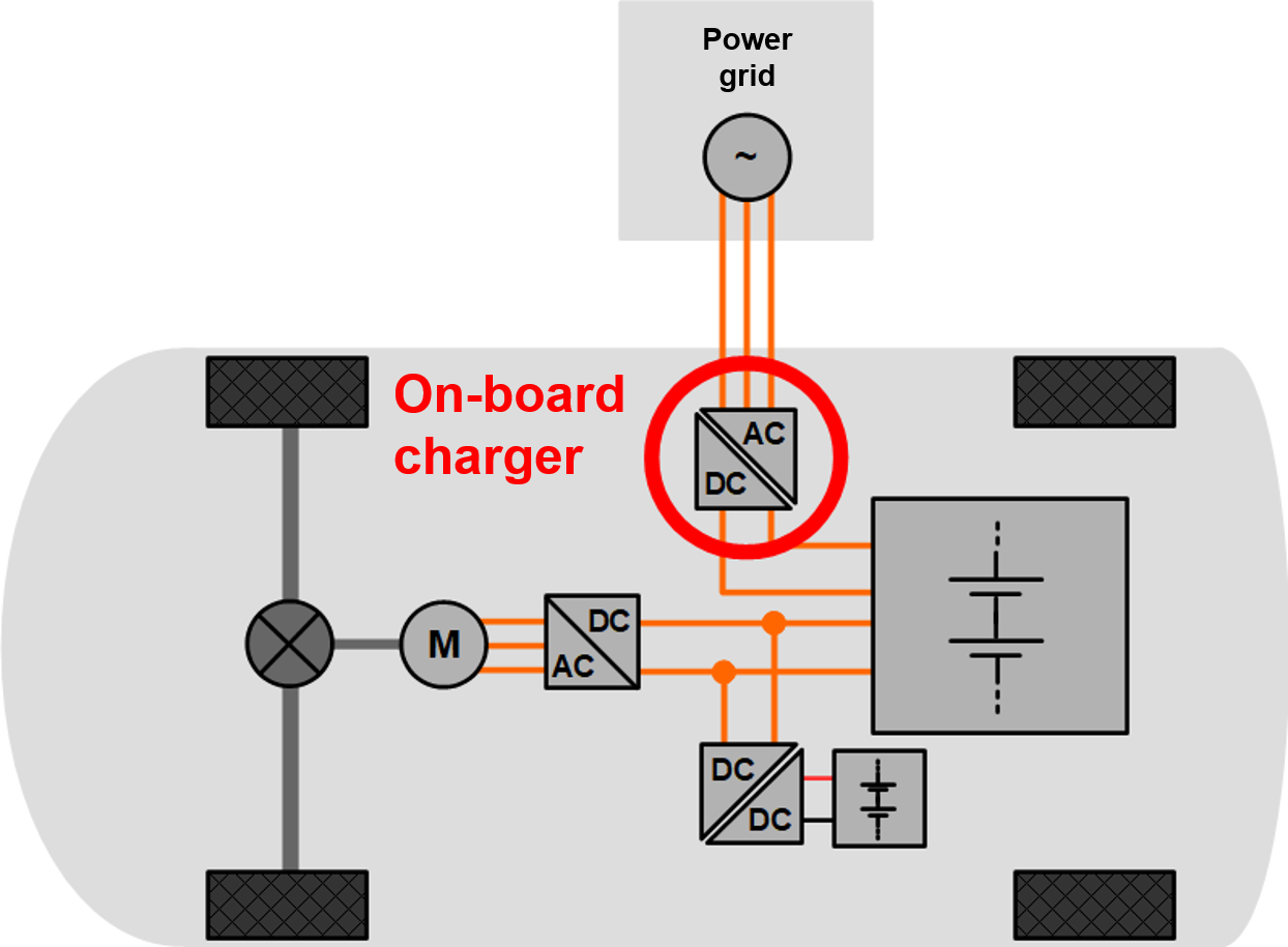
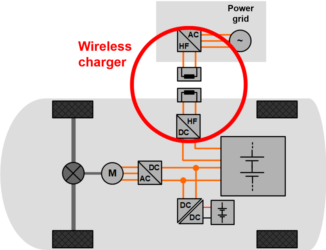
In its most basic form, an electric motor consists of a dynamic part, the rotor, which is pivoted on a static part, the stator. Both parts consist of magnetic steel sheets which function as magnetic flux paths. Between both parts a small air gap ensures the ability to rotate.
The stator sheets have teeth geometry (similar to a gear) on the outer circle through which the coils of insulated conductors are wound.
To drive the motor, an inverter controls a current flow through the coils to create a magnetic flux circle from the stator sheets over the air gap to the rotor sheets and back. Through this, the torque is generated by electromagnetic force which converts electric energy into rotational energy.
Coil Components for Electric Motors
The main difference of the coils and the winding process is separated into two kinds of stators:
- Stator with distributed windings, where several teeth share one coil
- Stator with concentrated windings, where each tooth has its own coil.
Both stator types have different properties and various production methods.
In classic industry motors, the winding consists of only one magnet wire, which is sufficient for lower power. For higher power in EVs higher copper cross sections are needed. This can be achieved by parallel magnet wires or by thick copper bars, called hairpins or ipins. Both solutions bring the disadvantage of high eddy current losses. Litz wire instead reach the desired copper cross sections with high filling factors while also compensating for eddy current losses.
High frequency litz wire can be designed for nearly every motor power level by adding the appropriate number of strands to achieve the target copper cross section.
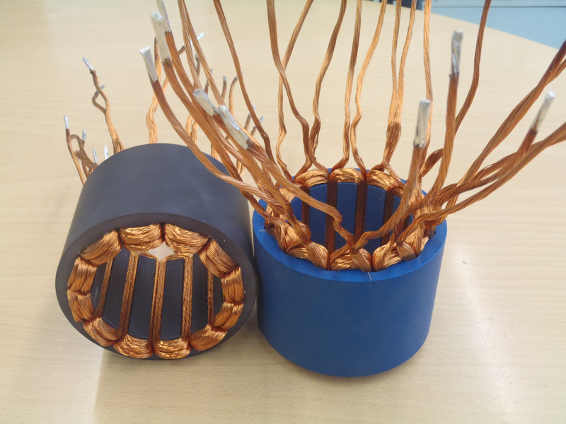
Stators with Concentrated Tooth Windings with Self-Bonding Litz Wire
Within the conversion from electric power to rotational power, thermal losses occur. These are primarily copper losses, which are split into DC losses and AC losses.
DC losses can be reduced through higher copper cross sections.
The cause of AC losses are eddy currents from skin and a proximity effects.
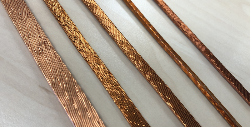
Different Types of Profiled Litz Wire for Distributed Stator Windings
High frequency litz wire compensates for eddy currents thus improving the efficiency of motors.
Another benefit of high frequency litz wire in motors is the improved heat conductivity, which improves the heat dissipation and mitigates high frequency losses at the same time.
EV traction motors can have a high risk of partial discharge due to the high voltage levels combined with the short and near rectangular switching mode of the inverters. High frequency litz wire can be designed with partial discharge resistivity to ensure long term durability. Taped litz wire and litz wire with special enamel are available.
For distributed windings, profiled litz wire provides a good solution for high filling factor and optimal slot utilisation.
Self-Supporting Coil by Self-Bonding Litz Wire
Wheel Hub Motor with Self-Supporting Coils by Self-Bonding Litz Wire
Concentrated windings can also be produced as self-supporting coils by using litz wire with self-bonding enamel. The litz wire is first wound to a coil, in a second step compressed, and later bonded to fix the wires on the coil with the possibility of resoftening.
Motor coils generally must be in rectangular to fit in the slot with high filling factor. Litz wire can be designed with high mechanically flexibility to reach small winding radius without damaging the insulation similar to a thick single wire.
Frequencies in motors have to be differentiated between inverter switching frequency and stator frequency. The main stator frequency has the most significant influence on eddy current losses and is typically up to 3 kHz, dependent on the speed. High frequency litz wire is designed to that value.
1.1.6 Basic Relations between Litz Wire and Power Electronic
Relation of Switching Frequencies and Inductor Size
The coil size in transformers, inductors, and chokes can be significantly reduced by higher switching frequencies.
Switching frequencies are limited by thermal losses, which occur during the switching process. This is why switching speed had to be shortened to minimise switching losses in power electronics and to reduce coil sizes for higher power densities and to lower volume.
Developments in power transistor technologies have reached significant alteration in switching speed and voltage range due to new semiconductor materials.
Shorter switching times mean that the voltage rising flanks are getting higher, according to the following table:
| Power transistor technology | Voltage rising flanks dU/dt | Voltage range | Since Year |
|---|---|---|---|
| Bipolar Transistor Thyristor GTO | <1kVµs | <300V | 1970 |
| IGBT | <10kV/µs | <1600V | 1990 |
| SiC GaN | >35kV/µs | <1600V | 2010 |
Overview of Semiconductor Developments
Relation of High Voltage Trend and Litz Wire Insulation Materials
The trend of increasingly higher voltages set demanding requirements for the insulation materials of litz wire. In addition, the high voltage potential between the single turns of the transformer needs consistently high insulation from nearby turns.
This is caused by the high frequent switched voltages, especially in converter topologies with resonant circuits.
Elektrisola designs the litz wire individually for each power transformer for optimum efficiency, high voltage protection, thermal conductivity, and filling factor.
Relation of Switching Methods, Breakdown Voltage and Partial Discharge
Voltage is controlled by semiconductor switches to impress current into inductors in all power electronics. These consist primarily of litz wire in high frequency applications. The switching methods differ depending on the application between hard switching and soft switching.
Hard switching means that the switching operation is done at the time when the current and the voltage are not equal to zero. Thereby switching losses are high and durability is low. Partial discharge risk is high because of the significant voltage increase per time on inductors.
Soft switching means that the switching operation is done at the time when the current and the voltage are zero. Switching losses are low inside the transistors and improve efficiency and durability of the power electronics and inductive components. The risk for partial discharge is low.
1.2 Interior Heating
General
Automotive Seat with Litz Wire Heating
Elektrisola was the first to develop litz wires with enamelled single wires for seat heating applications in automobiles to avoid hot spots in seats. Later, different alloys and outside extrusion has been introduced to further improve the litz wire.
Along with heated seats, heated steering wheels are becoming increasingly popular. Originally used in higher classes of vehicles, electric interior heating has now become standard in many classes of vehicles.
Conventional cars with combustion engines utilize the waste heat of the engine for heating the vehicle cabin.
This is not possible in EVs. Therefore, efficient ways of heating with lower energy requirements are needed, e.g.
- heating of direct contact surfaces such as seats, arm rests, or steering wheel, and
- radiation from panels near the passengers as efficient design options.
Different Interior Heating Options
For many heating applications, enamelled Litz Wire became the state-of-the-art solution coping with the technical, mechanical, and electrical challenges.
Individually designed litz wires allows designers to achieve precise temperature profiles while also avoiding hot spots in case of individual wire strand breaks within a litz, due to high bending stress or mishandling.
Seat Heating Carrier Element with Litz Wire
Detail of Seat Heating Carrier Element with Litz Wire
Technical details
The most important technical aspects of an enamelled litz wire for heating applications are:
- No Hot Spots
As explained above
- Flexlife Performance
Heating litz wires must strongly resist mechanical stress caused by bending and tension during its life time, as seats are typically exposed to tough mechanical impact in daily use. Side bolsters are especially mechanically demanding areas. Optimized wire diameters, usage of alloys, special bunching designs, and optional extrusion jackets are the main influencing design factors to significantly improve flexlife. Strain relief components can also support very small and thin litz wire constructions, where needed.
- Heating Resistance
The optimal combination of conductor cross section and alloy ensure a precise final resistance and temperature profile in the heated area. The specific litz wire resistance in ohm/m and the temperature coefficient define the final heating performance to the overall length of the heating conductor.
- Loop Behaviour
The usage of high tensile but less flexible alloy material results in a potentially higher number of loops of the bunched litz wire causing kinks or knots. This might lead to damage during the sewing process. Special bunching designs, optimal wire handling, and bunching methods reduce this effect to a minimum specification. Optional outer extrusion has a positive effect on the loop behaviour.
- Pinholes
Under thermal and mechanical stress, the insulation of enamelled wires can suffer from pinholes. These are microscopic cracks of the enamelling layer. Pinholes can be avoided by the adequate choice of enamel type, the wire handling during the wire production process, and optimized bunching methods.
- Chemical Resistance
Liquids such as sweat, soft drinks, milk, coffee, cleaning agents, and others can affect the lifetime of the heating wire. Through diffusion, the insulation can suffer leading to corrosion effects and early failure of the heating element. The combination of correct enamel type, grade, and optional extrusion coating improves the chemical resistance and protects the heating wire against such influences.
1.3 Interior Electronics
General
Wireless charging of cell phones is an increasingly common addition to the passenger cabin as it removes the need to handle a charging cord for the customer.

Automotive Integrated Wireless Charging System
In this market, two technologies for wireless charging systems are widely used:
Inductive Wireless Charging System
The wireless transmission of power is performed by mutual induction of magnetic fields between a transmitter and receiver coil. In the transmitter coil an alternating current creates a time varying magnetic field, which is radiated in all directions. The highest power transfer efficiency in this system is achieved when a receiver coil with identical dimensions to the transmitter coil is placed precisely on top and a few millimetres away from the transmitter coil.
The main advantage of inductive wireless charging systems is a relatively high efficiency, when transmitter and receiver are tightly coupled.
This is preferred when a high efficiency from the charging system is needed.
Resonant Wireless Charging System
This system is still “inductive”, in the sense that a magnetic field generated by the transmitter coil induces a current in the receiver coil. However, the principle of transmitting energy is done at higher frequencies than inductive systems and relies on both transmitter and receiver coils operating at the same resonant frequency. In a resonant wireless charging system, a type of energy tunnel is created between the coils, which allows an energy transfer at larger distances, between multiple coils, and in multiple directions.
There is some loss of efficiency in the system due to flux leakage even at closely positioned coils.
Therefore, this system is preferred when convenience of easy positioning is required from the system.
Technical Standards
There are 2 main standards for wireless charging for consumer electronics:
- Qi
(Developed by the Wireless Power Consortium “WPC”)
Technology: Inductive and Resonant
Operating Frequency: 85 kHz - 205 kHz
Transmitter Power Levels: 5 W -15 W
- Rezence
(Developed by the Alliance for Wireless Power “A4WP”)
Technology: Resonant
Operating frequency: 6.78 MHz
PTU (Power Transmitter Unit) Power levels: 2 W - 70 W
PRU (Power Receiver Unit) Power levels:
3.8 W - 50 W
Wireless Charger Components in the Qi Standard
Power Transmitters in the Qi standard are specified from design types from A1 to A34 (having one or more Primary Coils) and design types from B1 to B7 (having an array of Primary Coils). The different design types differ from one another among other things in coils´ size and shapes (round, oval, and square), all having litz wires with differ-ent numbers (from 24 to 180) of single wires of 0.08 mm.
Even though Power Receivers are not defined by the Qi standard, it sets some examples using similar litz wire configu-rations as the Power Transmitters.
Typical Litz Wire Products
For typical litz wire products for wireless charging designs see the following links:
- “Self Bonding Wire”
- “Basic”
- “Served”
- “Smartbond”
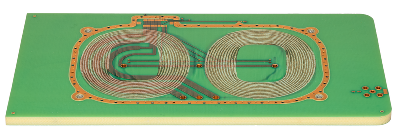
Litz Wire Planar Coils embedded in a PCB of Wireless Charging System
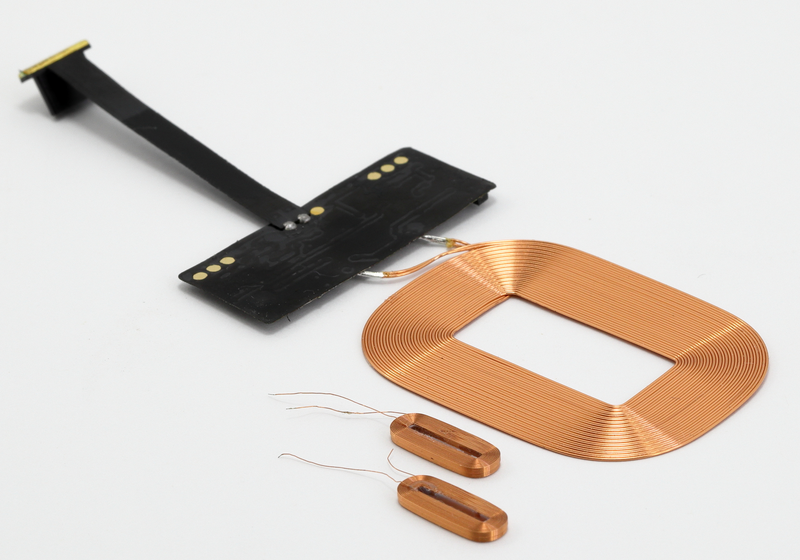
Planar Coil with Self-Bonding Litz Wire in a Smartphone Wireless Charging System
2. Industry
2.1 Switch-Mode Power Supply
General
Switch mode Power Supplies (SMPS) supply electric and electronic devices with specific stepped down direct current (DC). Due to their high efficiency, compact and light design and wide range of input voltage, SMPS are used in many industrial applications.
Examples are:
- charging systems
- laboratory and test equipment
- welding technology
- medical and IT systems
Technical details
Power source is the public AC grid whose power is converted into High Frequency (HF) power using fast switching semiconductor topologies, see picture 1 below. To translate the high frequency input voltage to a lower AC voltage level a high frequency transformer is needed. Its dimensions can be reduced by increasing the working frequency (30 kHz - 500 kHz).

Switched Mode Power Supply System
Usually, high frequency transformers work with layer windings and small numbers of turns. The usage of high frequency litz wires is necessary to efficiently reduce high frequency losses at higher frequencies. For safety reasons the primary (input) side of the transformer has to be separated from the secondary (output).
Typical Litz Wire Products
HF Transformer with Separated Bobbins
Constructional insulation elements like separating barriers and flanges can be implemented for keeping electrical air and creepage distances.
HF Transformer with separating Winding Barrier
A more compact and space saving technical approach is the usage of reinforced insulated winding wires (FIW). In this case air and creepage distances can be reduced, smaller and light designs with higher power density can be realized.
To meet the increasing demand for higher working frequencies and compact transformer dimensions Elektrisola offers the following design options:
- Silk or nylon served litz wires guarantee high flexibility and form stability for optimum layer winding performance.
- High frequency litz wires with additional tape insulation offer high breakdown voltages up to 10 kV.
- Elektrisola’s reinforced insulated and VDE-certified product family EFOLIT® covers SMPS - designs with very high safety demands.
- Rectangular or square profiled (compressed) litz wires ensure optimal copper filling factor for both litz wire and coil winding.
2.2 Sensors
General
The optimal High Frequency (HF) performance of enamelled litz wire and the wide range of possibilities for unique designs make litz wire an optimal material for sensors and antennas.
Examples are
- Inductive proximity sensors
- Metal detection sensors
- Coils for RFID-Systems
- Coils for Near Field Communication
Technical details
Radio Frequency Identification (RFID)
The reading device creates a high frequency field such as a gate that acts on the antenna of the transponder. Voltage is induced in the antenna; the chip is activated and creates an individual response by field attenuation. The response is received by the reader.
Planar Coil in a RFID Transponder
RFID Chip Reader
Near Field Communication (NFC)
NFC defines different communication protocols for a communication between two electronic devices over a distance of 4cm.
The low speed connection can be used for the following exemplary applications:
- Contactless payment systems
- Information exchange
- Identity and access tokens
- Smartphone automation
- NFC tags
NFC Ticket Vending Machine
Inductive Proximity Switches
The function of the sensor is based on an oscillating circuit consisting of a coil and capacity as characterized by the Q-factor. The coil itself creates an electromagnetic field that covers the area of detection. In the presence of a conductive element in the area, the Q-factor is changed due to eddy current losses.
The loss of field energy is detected by electronic circuits of the proximity switch and the element is confirmed.
RFID devices and proximity switches are used in logistics, process automation, and railway technology.
The antenna (or field generating coils) are usually implemented without coil bobbins or carrier elements. In these air coils based on selfbonding technology, served or extruded litz wires are used.
Proximity Switch
Typical Litz Wire Products
Elektrisola offers the following design options:
- High frequency litz wires with selfbonding enamelled wires allow for the smallest bending radiuses with high copper filling factors.
- Litz wire variants with Smartbond overcoat ensure easy hot air bonding with the highest copper filling factor.
- Thermal bondable silk or nylon served litz wires from Elektrisola guarantee optimal form stability and windability for air coils.
3. Medical
3.1 Hearing Aids (connection cables)
General
Hearing aids aim to be as small and light weight as possible to enhance the user’s comfort and minimize visibility. Traditional connecting cables are typically replaced by much lighter litz wires as single wires are insulated and can be used as a cable.
Different Types of Hearing Aids
Hearing Aid with Litz Wire Cable
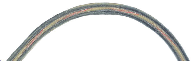
Hearing Aid Micro Cable
General Requirements
- Silver coating as protection against environmental influences
- Bright colors due to the silver surface beneath
- Very consistent solderability
- High bending performance
- Very strong with optional reinforcement fibers
- Very smooth extruded surface
- Highest requirements on tight diameter tolerances (roundness and size)
- Perfect stripping ability for electrical contact
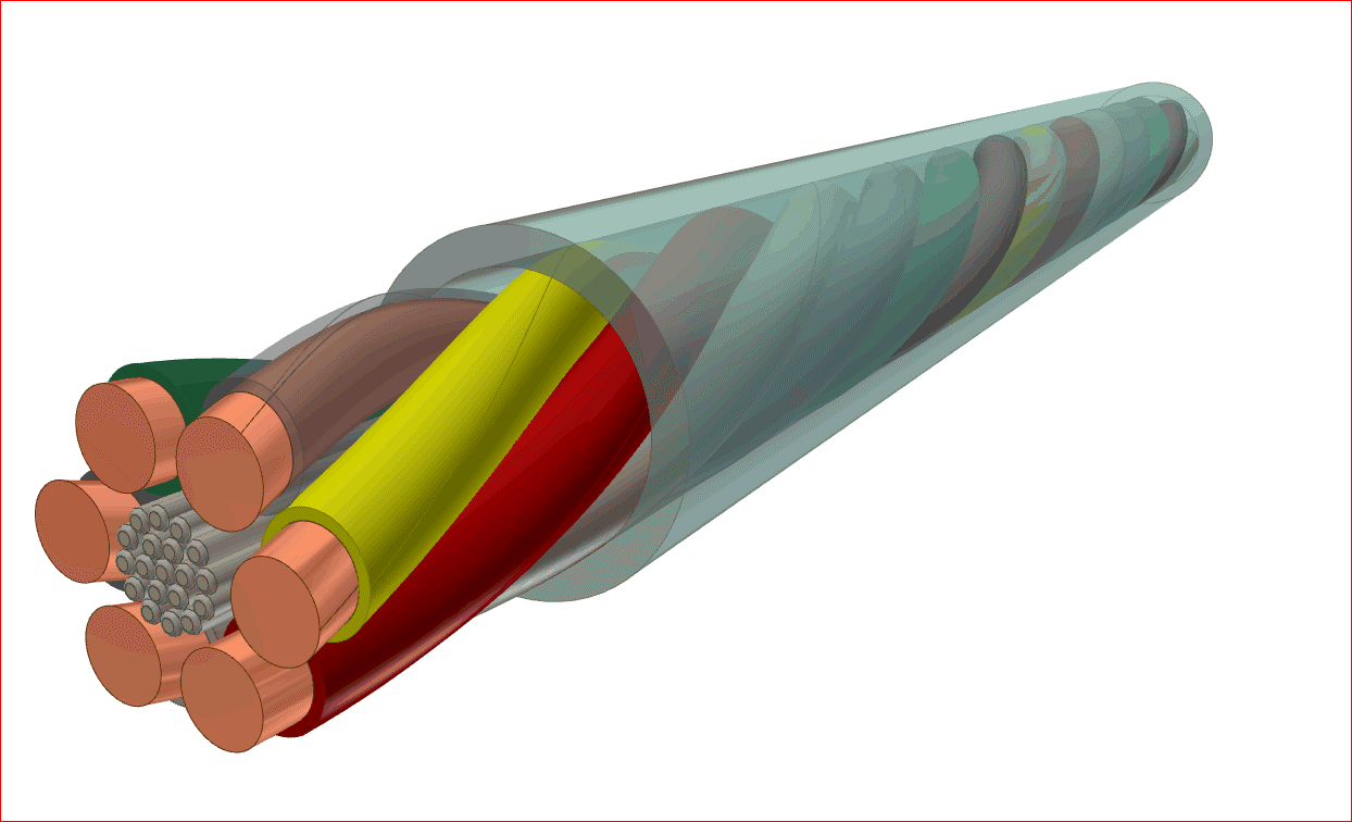
Hearing Aid Micro Cable with Color Coded Wires
3.2 Other Applications

Diagnostic System with Piezo Electric Transformer for Ultrasound
Secondary Coils for Magnetic Resonance Imaging
Wireless Charger for Medical Devices

Wireless Charger for Medical Devices

Surgical Tools and Instruments
For detailed information see:
4. Appliance
4.1 Inductive Cooking
General
An electromagnetic alternating field is induced in the bottom of a pot or pan and is transformed into thermal energy by eddy current losses. Thermal losses in the transmitting coil are very small, so the heating time is short and the surface of the cooking hob remains cold.
Technical Details
Operating frequency range: 20 kHz - 60 kHz
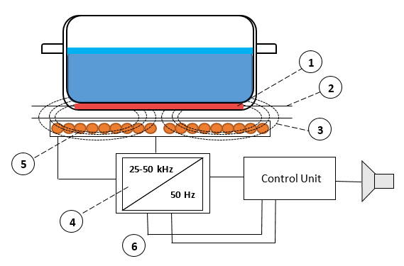

Inductive Cooking Hob with Field Generating Planar Coil and HF Transformer
- Bottom of cooking pot made from ferrous material
- Glass ceramic (hob surface)
- Alternating electromagnetic field
- Inverter
- Inductive litz wire coil
- Electrical grid
Inductive Cooking Components
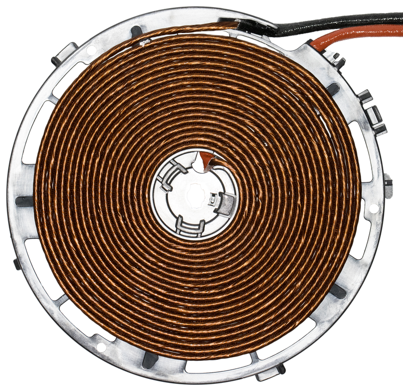
Planar Coil with Carrier
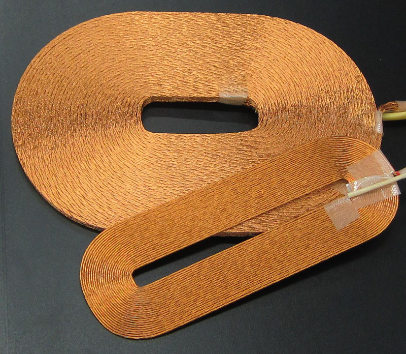
Planar Coil with Self-Bonding Litz Wire
Inductive Conductor Requirements
- High temperature class
- High break down voltage
- Mechanical strength
- High filling factor (compressed winding)
Typical Litz Wire for Inductive Cook-ing Hobs
- High frequency planar coils with basic litz wire
- Primary materials: copper, aluminium, and copper clad aluminium
- Single wire diameters from 0.18 mm - 0.4 mm
- 20 - 120 strands (depending on the size of the cooking hob and the op-erating frequency)
- High temperature odourless resistant enamels (≥ 200 °C).
- Optional profiling: Can be used to increase the filling factor (profiled litz)
5. Renewable Energy
5.1 Solar Inverter
Solar Panels with Inverter Units
General
The solar inverter is the heart of a solar power system. It converts DC current from the solar panels into the grid alter-nating current.
At the same time electronic control in the inverter monitors the whole solar power system and the grid.
A solar inverter has the following tasks:
- Efficient energy conversion from lower voltage DC to higher voltage AC
- Power optimisation
- Monitoring of power and temperature data
- Communication to smart energy systems
- Temperature management to avoid overheating of solar panels
Technical Details of Solar Inverters
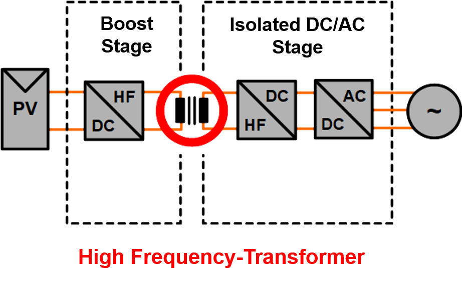

Grid Solar Inverter System
Solar inverters can be categorized, dependent on three properties:
- Power
The power ranges from a few kW to MW range. Typical values for private households are 5 kW, for industrial 10-20 kW and 500 kW and up for solar power plants.
- Module interconnection
on the DC side solar inverters can be connected to a string, multistring, or central topology, dependent on the power and efficiency requirements.
- Circuit topology
The inverter can be designed for single phase AC grid or three phase AC grid, and can be either with or without galvanic separation.
Galvanic separation is realised with a transformer between the DC and AC side. By doing this the module stack can be coupled to the ground to prevent alternating voltage potentials, which is compulsory in some countries.
Inverters without galvanic separation have the DC and AC side electrically connected, which leads to the advantage of higher efficiencies, but the disadvantage of alternating voltage potentials against ground which limits the lifetime.
Litz Wire Requirements for Solar Inverters
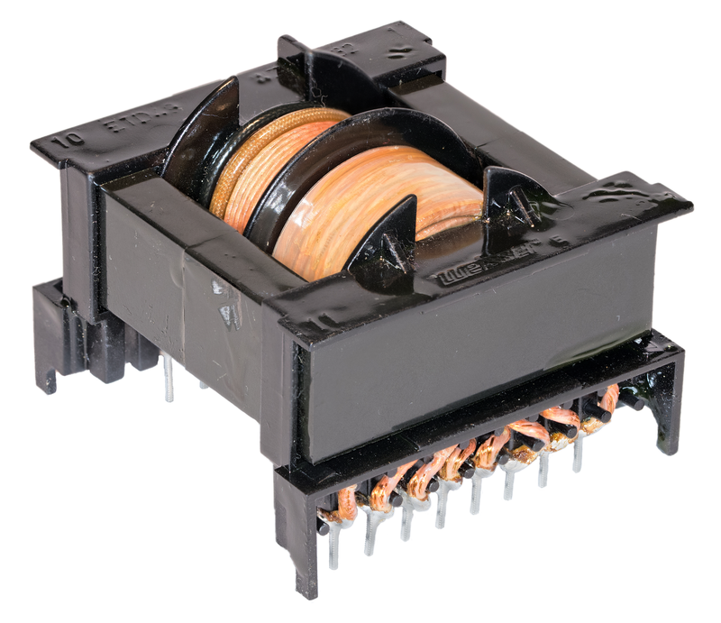
HF transformer with separated Bobbins and reinforced Litz Wire
- Temperature index TI = 155 °C
- High mechanical robustness
- Good flexibility
- High dielectric breakdown voltage
6. Consumer electronic
6.1 Switched Mode Power Supply
General
Switch Mode Power Supplies (SMPS) supply electric and electronic devices with specific down stepped direct current (DC). The key element for voltage down stepping operation is a High Frequency (HF) transformer.
Due to their high efficiency, compact and light design, and variable input voltage, SMPS are wide spread not only in industry applications, but also in the consumer area.
Examples are:
- Smartphone Charger
- Notebook Charger
- Personal Computer
- Audio and Multimedia Systems
- Televisions
- Household Appliances
- Charging Systems
Technical Details
Usually there are two locations to place the SMPS unit to the consumer device:
External (cable based)
SMPS in an External Notebook Chargers

SMPS in Smartphone and Notebook Chargers
Internal, where the electronic devices and inductive components are directly mounted on the main board
Printed circuit board with SMPS
See examples of high frequency transformers of SMPS in the following pictures:
HF Transformer with reinforced Litz Wire
HF Transformer with Basis Litz Wire and EMV Shield
HF Transformer with reinforced Litz Wire
HF Transformer with reinforced Litz Wire
For more technical details and litz wire product information please refer to
SMPS Industrial Application.
(see point 2.1)
6.2 Smart Textiles
Litz wire is used for special applications in Smart Textiles. Generally, very thin litz wires are used, as the wire must blend into the fabric and not disrupt the base texture. At the same time, rough handling in daily use, as well as washing or cleaning, creates a very demanding environment.
General
- Sports and casual clothings
- Protective gear for security forces, RFID Identification
- Building security technology
- Festive clothes/uniforms
- Mechanical engineering/monitoring of multi material systems, medical engineering
Technical Details
- Small outer diameter of litz wire
- Textile characteristics, fine structures
- High tensile strength, splice, and flex life performance
- Chemical stability
Color retention
For use in textile applications special enamelled wires are needed, see
Typical Characteristics of Smart Textile Wires
- Single wire diameter: 0.02 mm - 0.071 mm
- Number of single wires: 2 - 100
- Conductor material: copper and alloys with and without silverplating
- Insulation: Polyurethane based enamels, extrusion coatings with low melting points
- Optional: Bare single wires
- Optional: Strain reliefs
- Optional: Nylon or silk serving for mechanical support
6.3 Wireless Charging
General
Smartphone on Wireless Charger
Wireless chargers are found in the market as wireless charging pads, built-in wireless chargers for furniture, or as USB docks with a wireless charger. The charger needs a receiver on the user’s electronics, such as a smart phone, watch, etc.
Wireless chargers offer the following advantages for consumer electronics:
- No cables
- No need to have the right connector
- Reduced wear of charging port
In this market two technologies for wireless charging systems are widely used:
Inductive Wireless Charging System
The wireless transmission of power is performed by mutual induction of magnetic fields between a transmitter and receiver coil. In the transmitter coil an alternating current creates a time varying magnetic field, which is radiated in all directions. The highest power transfer efficiency in this system is achieved when a receiver coil with identical dimensions to the transmitter coil is placed precisely on top and a few millimetres away from the transmitter coil.
The main advantage of inductive wireless charging systems is a relatively high efficiency, when transmitter and receiver are tightly coupled.
This is preferred when a high efficiency from the charging system is needed.
Resonant Wireless Charging System
This system is still “inductive”, in the sense that a magnetic field generated by the transmitter coil induces a current
in the receiver coil. However, the principle of transmitting energy is done at higher frequencies than inductive systems and relies on both transmitter and receiver coils operating at the same resonant frequency. In a resonant wireless charging system, a type of energy tunnel is created between the coils, which allows an energy transfer at larger distances, between multiple coils, and in multiple directions.
There is some loss of efficiency in the system due to flux leakage even at closely positioned coils.
Therefore, this system is preferred when convenience of easy positioning is required from the system.
Technical Standards
There are 2 main standards for wireless charging for consumer electronics:
- Qi (developed by the Wireless Power Consortium “WPC”)
- Technology: Inductive and Resonant
- Operating Frequency: 85 kHz – 205 kHz
- Transmitter Power Levels: 5 W -15 W
- Rezence (developed by the Alliance for Wireless Power “A4WP”)
- Technology: Resonant
- Operating frequency: 6.78 MHz
- PTU (Power Transmitter Unit) Power levels: 2 W - 70 W
- PRU (Power Receiver Unit) Power levels:
- 3.8 W - 50 W
Wireless Charger Components in the Qi Standard
Power Transmitters in the Qi standard are specified from design types from A1 to A34 (having one or more Primary Coils) and design types from B1 to B7 (having an array of Primary Coils). The different design types differ from one another among other things in coils´ size and shapes (round oval and square), all having litz wires with different numbers (from 24 to 180) of single wires of 0.08 mm.
Even though Power Receivers are not defined by the Qi standard, it sets some examples using similar litz wire configurations as the Power Transmitters.
Typical Litz Wire Products
For typical litz wire products for wireless charging designs see the following links:
- “Self Bonding Wire”
- “Basic”
- “Served”
- “Smartbond”
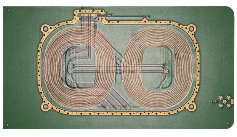
Planar Coils embedded in a PCB of Wireless Charging System
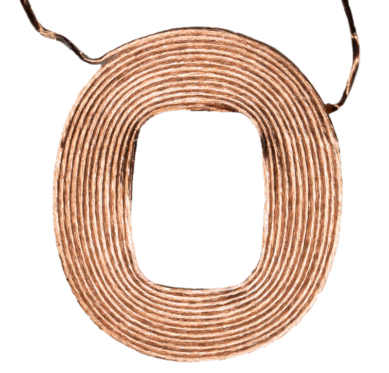
Planar Coil with Self-Bonding Litz Wire
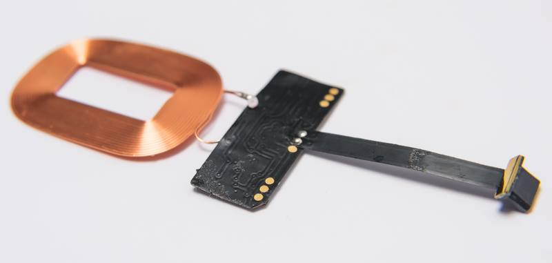
Planar Coil with Self-Bonding Litz Wire in a Smartphone Wireless Charging System
7. Special cables
General
Litz wires can be used in similar ways as a cable because the individual strands of enamelled wire have a very strong insulation. Extrusion of the litz wire can be used to further strengthen the mechanical and electrical properties, but also adds weight and volume. There are some applications that use a litz wire with enamelled wires directly as a cable, having advantages on diameter, weight and volume. Colored single wires help to differentiate the individual strands in the litz wire for the further processing.
Typical Litz Wire Components
Examples for special litz wire conductors and cables are
- High frequency litz wires with superfine and very complex bunching construction, for example 600 x 0.010 mm or 25.000 x 0.20 mm.
- Micro cables with the smallest possible outer diameters of mere millimetres, for example 7 x 0.010 mm.
- Diagnostic cables with thermally fixed selfbonding enamelled wires. For example twisted pair wires (e.g. 2 x 0.020 mm) or planar Multifilar Wires.
- Trailing cables with maximum flexibility and low friction constructions and enamel coatings.
- Vibration resistant signal line with conductors based on special alloys (e.g. 7 x 0.04 mm).
- Litz wire for headset cables which are extruded together to get a thin light weight cable.
- High frequency litz wire with special color coding.
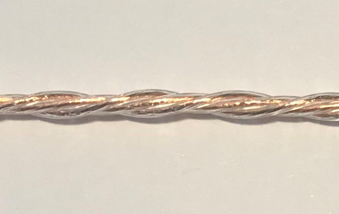
Microcable with Extruded Coating
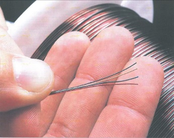
Multifilar Color Coded Wire
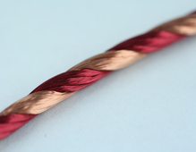
Color Coded Litz Wire
Services
ELEKTRISOLA your Partner for HF-Litz Wire
Partnering with our customers and offering tailor-made services is our goal. Starting with the first step of designing an optimal litz wire up to the efficient delivery of high quality products, we always make sure our customers receive the utmost service.
Technical Application Consulting
ELEKTRISOLA’s philosophy is to be a customer's partner rather than just a supplier. Therefore, a key focus for us is litz wire related R&D and technical support. Our customers can utilize our global resources in terms of Customer Support and Application Engineering for litz wire design and Engineering Support to develop innovative and cost effective solutions for specific customer applications.
Litz Wire Handling
Mishandling of litz wire can easily cause damage to the litz wire or to the spool of the litz wire, which creates problems in dereeling.
Please handle the spools, boxes and pallets extremely carefully. Although the material is heavy it is very sensitive to mishandling.
Typical damages are:
1. Mechanical impact on the spool or spool flange which often leaves a whitish mark in the plastic of the spool. Such a hard impact could either displace the windings or cause the windings to fall down the spool. Mechanical damage of the flange can also break wire during dereeling because of rough or sharp edges on the spool flange.
Deformation of Spool Flange
2. Displacing the wire package. Displacement of the litz wire windings on the spool caused by shock loads resulting from dropping the spool or carton can cause dereeling problems from the winding pattern disruption on the spool.
Displacement of the Wire Package on Spool
3. Fallen windings. Can be created by rough handling as described above under ref. 1 and 2. Winding will fall into each other, creating knots followed by wire breaks.
Fallen Windings
4. Damaged winding. Very often caused by mechanical contact of other spools during handling or transportation of a single spool or by lifting the spool from the box crooked, thus scraping over the edge of the box. Will create dereeling problems and damage the litz wire structure.
Damaged Windings
Samples
Looking into total system cost and system performance an optimized litz wire design can make the difference. ELEKTRISOLA takes pride in our customised litz wire constructions and our ability to create samples quickly. Just talk with us and we will gladly support you with samples on short notice that meet your needs.
Logistics
Outstanding production know-how, significant production capacity, high efficiency, short communication paths, and long-term experience in handing, packaging and shipping of sophisticated wire make ELEKTRISOLA the most trustworthy partner when it comes to short lead times and reliable shipments.
Stock Items
The stock list contains sample quantities for tests and simple simulation. It only represents a selected small range of litz wire products. Qualified series products can therefore differ! Please contact us for individual solutions and custom-specific litz wire designs.
FIW Info

Fully Insulated Wire
General
About
FIW (Fully Insulated Wire) is an alternative wire to build switching transformers typically using TIW (Triple Insulated Wires). Due to the big choice of overall diameters it allows to produce smaller transformers at lower costs. At the same time FIW has better windability and solderability compared to TIW.
FIW is produced in a multiple coating process, which guarantees insulation without any defects.
ELEKTRISOLA FIW is approved as MW85C and according to OBJT2. It has been sold successfully for several years to the automotive industry and for applications which do not require UL approval acc. to UL 60950. As Elektrisola FIW is approved as MW85C it can be used by many Insulation Systems according to UL 1446. The Safety Standard IEC 62368-1 Edition 3 is approved and allows the use of FIW. The old Safety Standard IEC 60950 was withdrawn end of 2020.
The FIW Wire
Elektrisola developed a product based on a modified polyurethane with a life time acc. to IEC 60172 of 20,000 h at 180 °C, short designation P180. It is produced with multiple passes of individual covering of insulation and is in-line tested for high-voltage-continuity to assure the perfect insulation without any insulation defects.
FIW is defined with many Grades specifying different insulation thicknesses. FIW 3 is the smallest defined build, while FIW 9 is the biggest.
Elektrisola Standard FIW Grades ex stock are FIW 4 and FIW 6, as they give a good compromise between good technical performance and affordable costs.
Specifications
FIW is specified in different specifications. Basically there are Standards for enamelled wires, such as IEC and NEMA, but there are also Safety Standards, such as the old IEC 60950, replaced by IEC 62368-1, and UL Safety Standards, such as UL 2353.
In addition, some values are also specified in product standards as the Transformer Standard acc. IEC 61558-1.
Product
IEC 60317-56 and 60317-0-7
NEMA MW85c
UL 2353
Test Conditions
IEC 60851
IEC UL 60950 Annex U
IEC 61558-1
IEC 61558-2-16
UL 2353
Advantages of FIW
- choice of different insulation builds (with different insulation thicknesses) allows optimization of products like smaller transformers and gives a cost advantage
- excellent solderability
- superior windability
high temperature class of 180 °C, thermal life time acc. UL 60950 Annex U tested in transformers for temperature class 155 °C/130 °C
proven insulation system acc. UL 1446 of enamelled wires also with UL, used over many years
Example 0.25mm FIW 6, 390°C, 2.4 sec.
Production Process
The basic production process is similar to a normal enamelled wire Production Process, but has many more single wire passes - up to 120 - to generate the finally very thick enamel layer, as shown in below photo, where always 3 alternate layers were coloured to demonstrate the big number of layers.
Multiple layers of a 0.25 FIW 7
In addition, every production line is equipped with an In-Line High Voltage Continuity Tester, which checks the insulation of the wire over the complete length permanently to guarantee that there is no insulation fault.
Packaging
The FIW wire is spooled on standard spools used in Europe and in Asia
Delivery ex Stock
Many FIW wire configurations can be supplied ex stock. In the table Dimensions the grey highlighted diameters and builds are typical stock items.
Technical Data
Standardized Properties of FIW
IEC 60317-56 describes a full Enamelled Wire Specification with mechanical, electrical, thermal and other characteristics like soldering
UL 2353, rather similar to IEC 60950 Annex U, gives mainly electrical properties which mostly are rather short-term tests
The new Safety Standard IEC 62368-1 continues with the same requirements, taken partly from the Transformer Standard IEC 61558-1 for FIW.
Breakdown Voltage
Breakdown Voltage (BDV) values for FIW will vary depending upon which standard is used to calculate these values.
When using the enamelled wire standards for FIW (IEC 60317-0-7 and 60317-56) the BDV is calculated using the minimum insulation increase per size, (min. insulation increase = min. OD including insulation – nominal bare wire dimension).
BDV calculation acc. IEC 60317-0-7
The minimum values can be found in IEC 60317-56
Minimum BDV acc. to IEC 60317-56
The Transfomer Standard IEC 61558-2-16 was finally corrected as the BDV calculation in the old version mistakenly used the minimum insulation increase divided in half, erroneously resulting in approximately half the BDV values as the magnet wire standards.
IEC 61558-1 as a new version of IEC 61558-2-16 has already been released, correcting errors (like the BDV calculation described above) found in the previous version. One major difference: The new version requires the FIW to maintain durability for dielectric strength for one minute at 180 °C with a factor of 0.85 compared to IEC 60317-0-7. Here the dielectric strength is measured by Breakdown Voltage (rms) at room temperature.
Minimum BDV acc. to IEC 61558-1
IEC 62368 follows the BDV values of IEC 61558, but does not specify 180 °C as test temperature as IEC 61558
Calculation of Breakdown Voltage
The minimum breakdown voltage acc. to IEC 60317-0-7 can be calculated with the nominal diameter and the FIW Grade by tool
Dimensions
Dimensions of FIW depend on the Insulation Grade, which describes the amount of insulation on the bare wire
Voltage or necessary FIW Grade by diameter for a given voltage can be calculated by a calculator
Weight / Length
Due to the extraordinary thickness of the insulation of FIW the length of a certain quantity of FIW and the weight of a wire with a certain length deviate remarkably from experiences with normal enamelledcopper wire.
The length of 1 kg of FIW 3 - FIW 9 for nominal diameters in the range of 0,071 - 0,710 mm - assuming nominal outer diameters acc. to IEC 60317-56 - can be looked up in the FIW Length Table on the next page in km/kg.
The weight of 1 km of FIW 3 - FIW 9 for the same range of nominal diameters - with nominal outer diameters acc. to IEC 60317-56 as before - can be looked up in the
The weight or length of a specific FIW wire can be checked by a calculator
Approvals
FIW is approved for different classifications:
UL for MW85C, UL File OBMW2.E331840
UL for OBJT2, UL File OBJT2.E316900
VDE Certificate Number 40036030
- UL Insulation Systems acc. UL 1446
- IEC 61558-2-16 for transformers (SMPS) specifies use of FIW and IEC 61558-1
IEC 62368-1 as new Safety Standard, replacing IEC 60950
LW Product Range
Litz Wire
Litz Wire Types
| Type | |||||||
|---|---|---|---|---|---|---|---|
|
|
Global Footprint

Global Footprint
ELEKTRISOLA is a true global producer of fine enamelled wires with 9 plants in the 3 most important continents for the automotive and the electrical industry using the same state-of-the-art machines to produce the same high quality standard.
Advantages of Elektrisola Global Footprint
1. Worldwide supply of identical quality
- same management of ownership
- same products
- same in-house designed machines
- same processes
- same work instructions
- same quality approvals (ISO, IATF)
- same UL-approvals
- same test procedures
- ideal for global projects
2. Safety of supply
- easy backup of other Elektrisola plants with identical products
3. Local production and supply
- fast and efficient delivery
- local currency
- local sales and service
4. Local service
- local engineering support for R&D and process improvement
- fast working as in the same time zone
- easy communication in local language
- assistance for global projects with local production
5. Environment friendly
- short transportation distances
- local spool recycling
- worldwide system for emission control (sniff during your visit)
Elektrisola Locations

Plants

Warehouse

Sale office